214
3D Support
Chapter 10 Special Functions
1
Display the Engineering Setup >Switcher > Config
>3D Config menu.
2
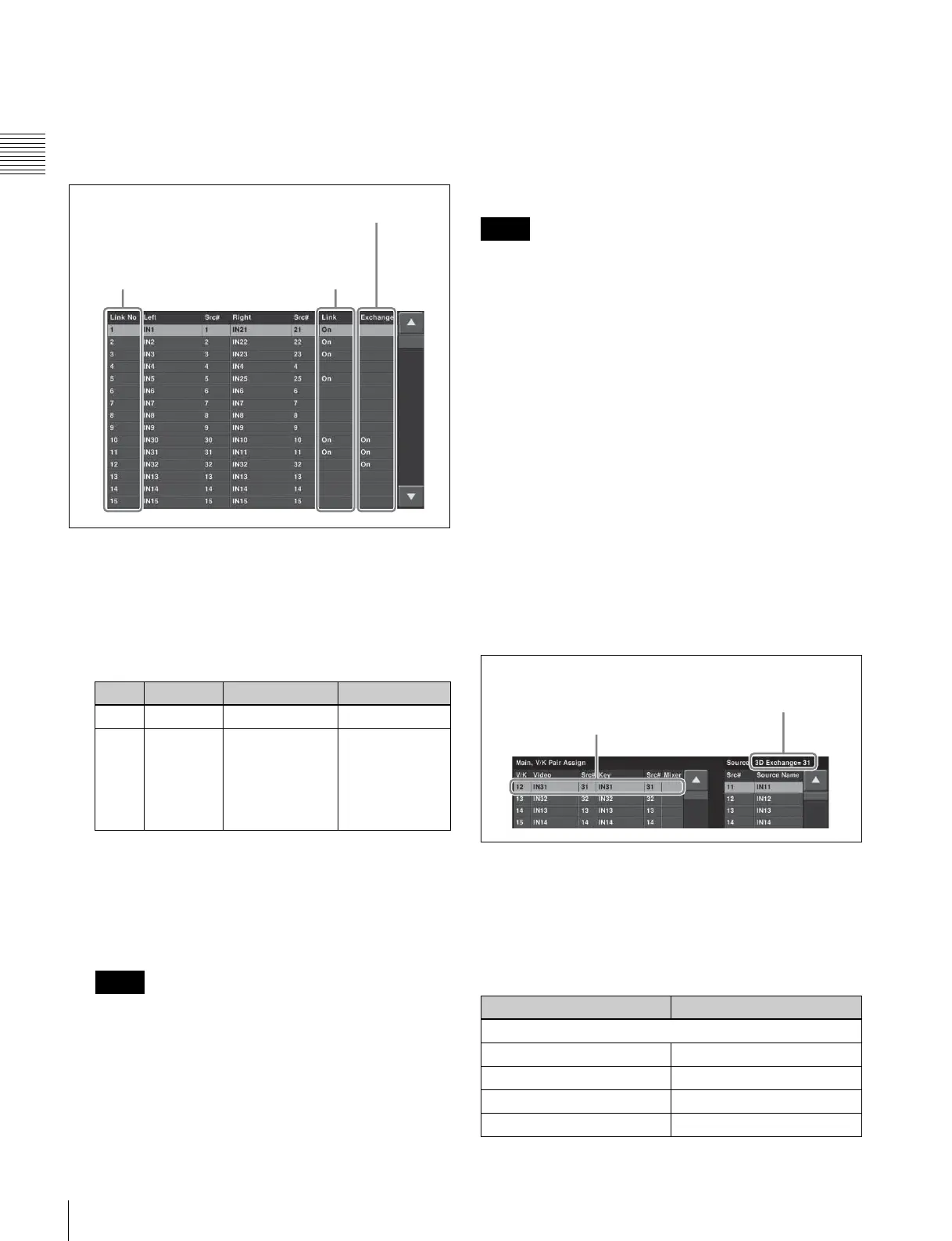
Press [Input Link].
The Input Link menu appears.
3
Using any of the following methods, select the link
number to operate on.
• Press directly on the list.
• Press the arrow keys to scroll the reverse video
cursor.
• Turn the knobs.
4
Press [3D Input Link], and set the link to either of the
following.
• To use separate left and right signals, set to On.
• To use the same signal shared between left and right,
set to Off (no indication).
When this is set to “Off,” one signal of the
predetermined pair cannot be used.
For example, for IN1 and IN21, IN21 cannot be used,
and is grayed out in the list.
5
Repeat steps 3 and 4, to set all of the primary inputs in
3D mode.
Using pairs of primary input numbers reversed
right-to-left
Press [L/R Input Exchange], setting it to On, to swap the
left and right signals, and reverse the indications in the list.
For example, when the left signal is IN1, and the right
signal is IN21, this assigns IN21 to the left signal and IN1
to the right signal.
When [3D Input Link] is off and [L/R Input Exchange] is
set to On, then the other input of the pair can be used.
For example, when using IN1 shared between left and
right, you can also use IN21 shared between left and right,
and IN21 also appears in the list.
To assign inputs with the primary input numbers
reversed left-to-right to cross-points
1
In the Input Link menu, set [L/R Input Exchange] to
On, then display the Engineering Setup >Panel >Xpt
Assign >Main, V/K Pair Assign menu.
In the Source field, “3D Exchange=xx” appears (“xx”
is the input number linked to the input number at the
position of the cursor).
In the example of the following figure, for IN11 “3D
Exchange=31” appears.
2
Press [Set].
This sets IN31 in place of IN11.
Combinations of left and right signals
(output connectors)
The left and right signals are combined for the slots as
follows.
If [1-2 Mode] is selected on MVS-8000X
Knob Parameter Adjustment Setting values
1 Link No Link number 1 to upwards
3 Num Select the
number of
consecutive
numbers from
the selected link
number
1 to upwards
Notes
When On, different signals are
used for left and right.
When there is no indication
(Off), the same signal is
shared between left and right.
When On, left and
right are reversed.
Link number
Notes
Right signals Left signals
Slot 13
OUTPUTS 1 OUTPUTS 2
OUTPUTS 3 OUTPUTS 4
::
OUTPUTS 19 OUTPUTS 20
Left-right reversed
number is assigned
“xx” is the input number
linked to the input number at
the position of the cursor
 Loading...


