568
Tally Generation Settings (Tally Enable Menu)
Chapter 23 Setup Relating to Router Interface and Tally (Router/Tally)
4
Press [Execute].
This makes the wiring setting according to the
specifications in steps 2 and 3.
Changing the Wiring Settings
1
In the Router/Tally >Wiring menu, press [Modify].
The Modify menu appears.
2
Referring to steps 2 and 3 in the preceding section
“Making new wiring settings,” change the parameters
as required. In this case, however, it is not possible to
specify multiple destinations in a single operation, and
a single “Destination Address” must be specified.
3
Press [Execute].
Deleting Wiring Settings
1
In the Router/Tally >Wiring menu, using either of the
following methods, select the wiring whose settings
you want to delete.
• Press directly on the list in the status area.
• Press the arrow keys to scroll the reverse video
cursor.
2
Press [Delete].
Sorting Wiring Settings
In the Router/Tally >Wiring menu, press [Sort].
The sorting of wiring settings are executed in the following
order.
Destination level order (ascending)tDestination address
order (ascending)tSource level order (ascending)
Tally Generation Settings
(Tally Enable Menu)
For settings relating to tally generation, use the Router/
Tally >Tally Enable menu.
Specify the destination to be the reference for tally
generation, and make various settings.
The settings are common to the parallel and serial tallies.
To display the Tally Enable menu
In the Engineering Setup menu, select VF6 ‘Router/Tally’
and HF4 ‘Tally Enable.’
The status area shows the tally generation settings.
The following functions are available here.
• Tally Type: Specify the tally type.
• Destination: Specify the address and level.
• Tally Enable: Specify the timing at which a tally is
enabled.
- Enable: Always enabled.
- Disable: Always disabled.
- Tally Input: Follow the tally input status.
Making New Tally Generation
Settings
1
In the Router/Tally >Tally Enable menu, press [New].
The New menu appears.
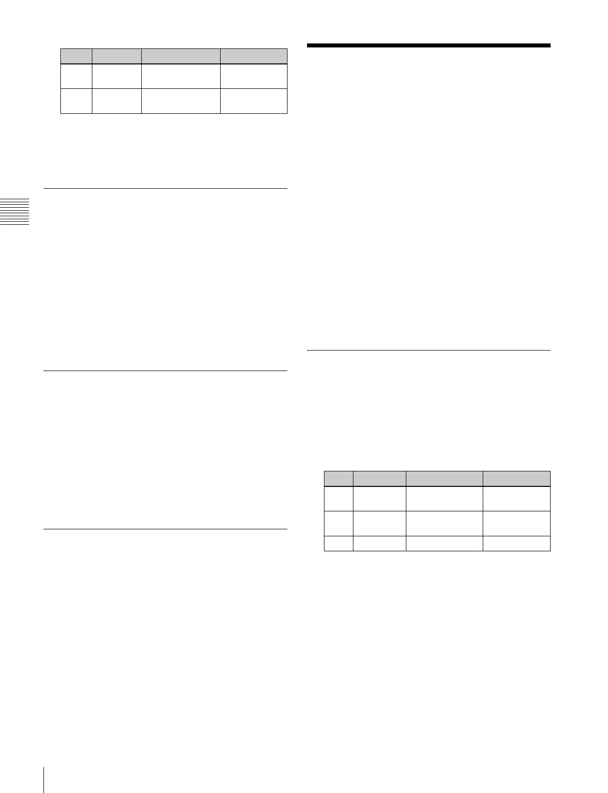
2
Turn the knobs to set the following parameters.
a) 1:R1, 2:G1, 3:R2, 4:G2, 5:R3, 6:G3, 7:R4, 8:G4, 9:R5, 10:G5, 11:R6,
12:G6, 13:R7, 14:G7, 15:R8, and 16:G8. (R is an abbreviation of
“Red Tally,” and G of “Green Tally.”)
3
In the <Tally Enable> group, specify the tally
generation mode.
Enable: Always generate a tally.
Disable: Never generate a tally.
Tally Input: Generate a tally from the tally input state.
4
When you selected Tally Input as the tally generation
mode in step 3, select either of the following in the
<Tally Input> group.
Knob Parameter Adjustment Setting values
4 Source
(From)
Source start
address
1 to 1024
5 Source
(Level)
Source level 1 to 8
Knob Parameter Adjustment Setting values
1 Destination
Address
Destination
address
1 to 1024
2 Destination
Level
Destination level 1 to 8
3 Tally Type Tally type 1 to 16
a)
 Loading...


