53
Basic Menu Operations
Chapter 2 Menus and Control Panel
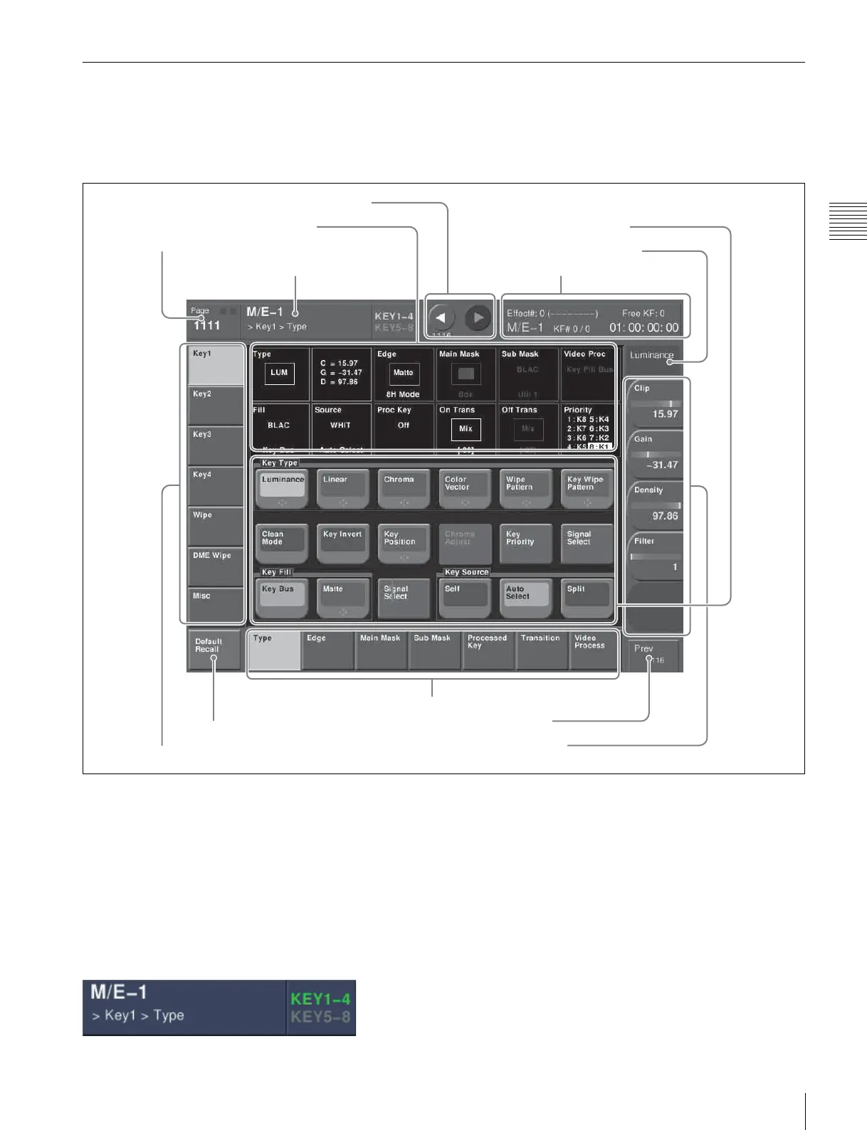
Interpreting the Menu Screen
The menu screen consists of the following principal parts.
When buttons on the screen are lit or represented in a
depressed state, this indicates that the corresponding item
or function is selected (set on).
The following describes the M/E-1 >Key1 >Type menu
screen as an example.
M/E-1 >Key1 >Type menu
a Menu title button
This shows the title of the menu screen.
You can set different colors for the main menu site and
subsidiary menu site (see page 59).
Switching the VF buttons between the Key1 to Key4
and Key5 to Key8 button displays
Switch the displays with the [KEY1-4] and [KEY5-8]
menu title buttons.
When [KEY1-4] is lit, Key1 to Key4 buttons appear in
VF1 to VF4.
When [KEY5-8] is lit, Key5 to Key8 buttons appear in
VF1 to VF4.
b Menu page number button
This shows the menu screen page number.
When you press this button, the top menu window (see
page 55) appears. You can enter the page number for the
desired menu, or press one of the top menu selection
buttons in the window, to display that menu.
While the system is accessing the hard disk, the indicator
lights red.
2 Menu page number button
1 Menu title button
6 Function button area
7 Parameter group button
8 Knob parameter buttons
3 VF buttons
4 HF buttons
9 Previous page button
5 Status area
0 Keyframe status
qa Default recall button
qs b (previous) button and B (next) button
 Loading...


