490
Overall Control Panel Settings (Config Menu)
Chapter 19 Control Panel Setup (Panel)
Setting a link table
For the link selected in the External Bus Link menu, make
the settings as follows.
1
In the Panel >Config >Link/Program Button >External
Bus Link >Link Matrix Adjust menu, press [Link
Table Adjust].
The Link Table Adjust menu appears.
The status area lists the status of the currently selected
link, combinations of video signals and sources, and
the sources that can be selected.
2
Using any of the following methods, select the
switcher cross-point button and the matrix source to be
linked to the button.
• Press directly on the list in the status area.
• Press the arrow keys to scroll the reverse video
cursor.
• Turn the knobs.
3
To confirm the matrix source selection made in step 2,
press [Link Source Set].
This confirms the selection, which is reflected in the
status area.
4
As required, repeat steps 2 and 3 to select the matrix
sources to be linked to other cross-point buttons.
To initialize the set links
In the Panel >Config >Link/Program Button >External
Bus Link >Link Matrix Adjust menu, press [Init Link
Table].
A confirmation message appears.
Press [Yes].
The links set using the above procedure are initialized to
the default settings, and this is reflected in the status area.
Making link bus settings
For the link number selected in the External Bus Link
menu, use the following procedure.
1
In the Panel >Config >Link/Program Button >External
Bus Link menu, press [Link Bus Adjust].
The Link Bus Adjust menu appears. The status area
lists the current link status, and the switcher buses and
router destinations that can be selected.
In this menu too, you can use knob 1 to select the link
to be set.
2
Using any of the following methods, select the
switcher bus and the router destination to be linked to
the switcher bus.
• Press directly on the list in the status area.
• Press the arrow keys to scroll the reverse video
cursor.
• Turn the knobs.
3
To confirm the bus selected in step 2, press [Master
Bus Set], and to confirm the destination press [Linked
Dest Set].
This confirms the selection, which is reflected in the
status area.
Linking Transitions Between Keyers
1
In the Panel >Config menu, press [Link/Program
Button].
The Link/Program Button menu appears.
2
In the <Link> group, press [Key Trans Link].
The Key Trans Link menu appears.
The status area shows the keyers for each M/E bank
and the linked keyers.
3
Using any of the following methods, select the keyer
to be the master.
• Press directly on the list in the status area.
• Press the arrow keys to scroll the reverse video
cursor.
• Turn the knob.
The selected keyer appears in reverse video.
4
In the <Key Select> group, select the keyer to be
linked to the transition of the master.
Linking does not apply to a transition carried out with
the downstream key control block.
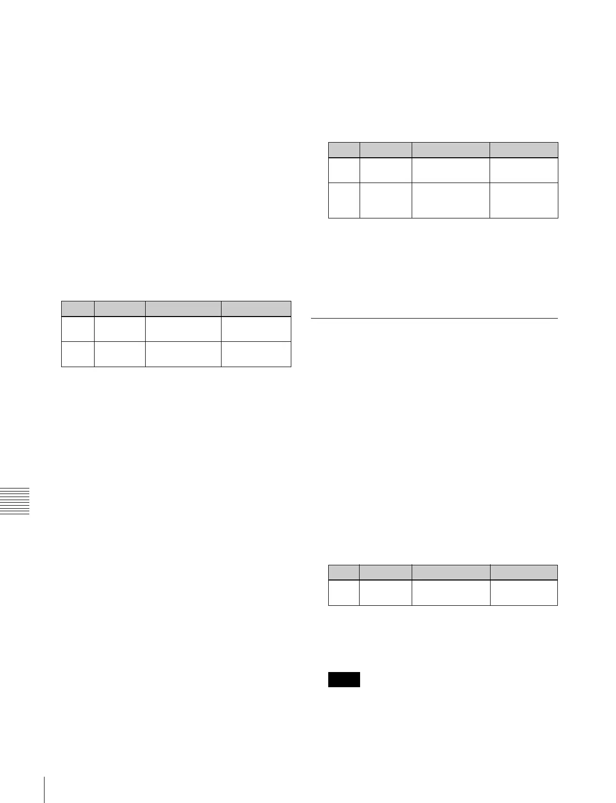
Knob Parameter Adjustment Setting values
1 Main No Switcher cross-
point button
1 to 300
2 Source No Matrix source
selection
1 to 128
Knob Parameter Adjustment Setting values
2 Internal
Bus
Switcher bus
selection
1 to 128
3 Destination Router
destination
selection
1 to 128
Knob Parameter Adjustment Setting values
1 Master Key Select keyer to be
master
1 to 40
Notes
 Loading...


