541
Settings Relating to Function Links (Link Menu)
Chapter 20 Switcher Setup (Switcher)
5
Using any of the following methods, select the bus to
be the link source, and press [Bus Set].
• Press directly on the list appearing in the status area.
• Press the arrow keys to scroll the reverse video
cursor.
• Turn the knob.
a) Only when [Master Bus] is selected, M/E-1 to M/E-4 Trans PGM,
and P/P Trans PGM are available.
Only when [Linked Bus] is selected, AUX 1 to AUX 48 as Key are
available.
With one of M/E-1 to M/E-4 Trans PGM and P/P
Trans PGM selected for [Master Bus], the link setting
become effective as soon as you start moving the fader
lever.
6
In the <Bus Select> group, select [Linked Bus] (link
destination bus).
7
Referring to step 5, select the bus to be the link
destination, and press [Bus Set].
8
Turn the knob to select the link table, and press [Link
Table Set].
For more information about link tables, see the
following item.
The selected link table number is confirmed, and this
is reflected in the status area.
To delete a link
Select the link you want to delete, then press [Clear] in the
Switcher >Link >Internal Bus Link menu.
Making Link Table Settings
1
In the Switcher >Link >Internal Bus Link menu, press
[Link Table Select].
The Link Table Select menu appears.
2
Using any of the following methods, select the link
source and link destination signals.
• Press directly on the list in the status area.
• Press the arrow keys to scroll the reverse video
cursor.
• Turn the knobs.
3
To confirm the selection, press [Link Src Set].
This links the link destination signal to the signal
selected as Main No.
To initialize the set source address
In the Switcher >Link >Link Table Select menu, press [Init
Link Table].
A confirmation message appears; press [Yes].
The source addresses are reassigned, and this is reflected
in the status area.
To change the link number and link table number
In this menu too, you can change the link number and link
table number. To do this, turn the knobs as follows to make
the setting, then press [Link Table Set].
Linking Cross-Point Buttons and
GPI Output Ports
To link cross-point buttons or the [CUT] and [AUTO
TRANS] buttons in the cross-point control block, and GPI
output ports, use the following procedure.
1
In the Switcher >Link menu, press [GPI Link], to
display the Switcher >Link >GPI Link menu.
The status area shows the output ports and the link
status, and delay value information.
2
Using any of the following methods, select the GPI
output port.
• Press directly on the list in the status area.
• Press the arrow keys to scroll the reverse video
cursor.
• Turn the knob.
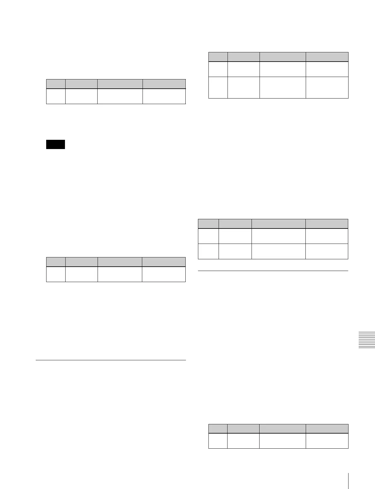
Knob Parameter Adjustment Setting values
2 No Bus selection 1 and
upwards
a)
Notes
Knob Parameter Adjustment Setting values
3Link Table
No
Link table
selection
1 to 8
Knob Parameter Adjustment Setting values
4 Main No Video/key signal
for link source
1 to 300
5 No Video/key signal
for link
destination
1 to 300
Knob Parameter Adjustment Setting values
1 Link No Link to which setting
applies
1 to 64
3Link Table
No
Link table selection 1 to 8
Knob Parameter Adjustment Setting values
1 GPI Port GPI output port
selection
1 to 8
 Loading...


