586
About the Macro Attachment List Display
Appendix (Volume 2)
About the Macro
Attachment List Display
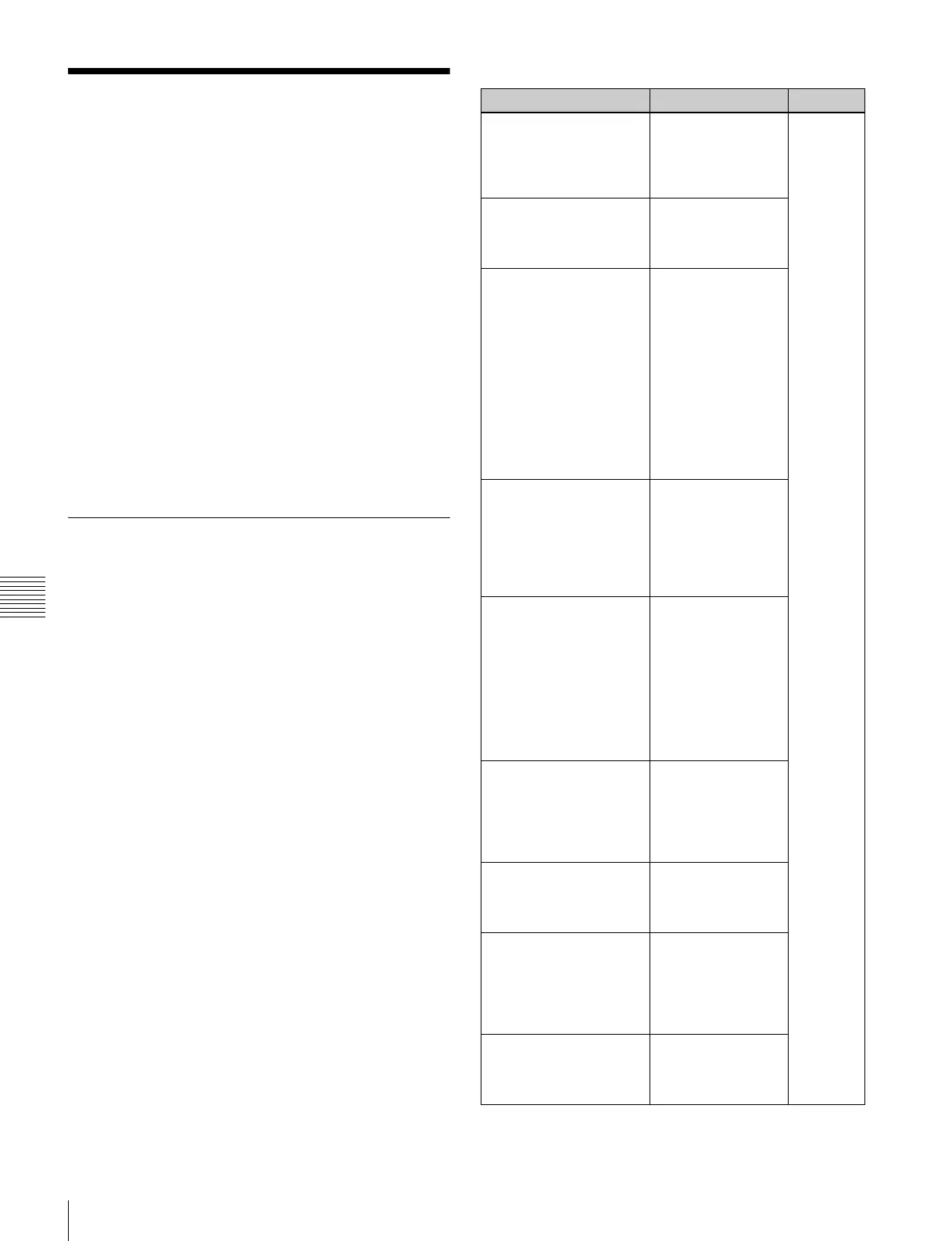
The Button column in the macro attachment list displayed
in the status area of the Macro >Attachment menu screen
shows character strings which identify macro attachment
assigned buttons. Each of these character strings is in fact
a combination of characters shown in the Button(1),
Button(2), and Button(3) columns in the following tables.
For example, if Block and Button(1) to Button(3) are
combined as:
Block: P/P XPT
Button(1): UTIL1 Bus
Button(2): V
Button(3): XPT2
The Button column in the macro attachment list in the
Macro >Attachment menu screen shows “UTIL1 Bus V
XPT2,” which means “utility 1 bus, video signal, cross-
point number 2.”
M/E and PGM/PST Banks
The following table shows only the macro attachment
assignable buttons in the PGM/PST bank.
For the M/E-1 (M/E-2 to M/E-4) bank, “P/P” in the Block
Select and Block columns changes to “M/E-1” (“M/E-2”
to “M/E-4”) and “DSK” in the Button(1) and Button(2)
columns changes to “KEY.” The contents of the Button(3)
column do not change.
Block Select:P/P, Block:P/P XPT
Button (1) Button (2) Button (3)
A Bus
B Bus
DSK1 Bus
:
DSK8 Bus
(nothing)
Shift
XPT 1
:
XPT 128
DSK1 Src Bus
:
DSK8 Src Bus
V
K
V Shift
K Shift
Sub A Bus
Sub B Bus
Sub DSK1 Bus
:
Sub DSK8 Bus
Main&Sub A Bus
Main&Sub B Bus
Main&Sub DSK1 Bus
:
Main&Sub DSK8 Bus
(nothing)
Shift
Sub DSK1 Src Bus
:
Sub DSK4 Src Bus
Main&Sub DSK1 Src Bus
:
Main&Sub DSK8 Src Bus
V
K
V Shift
K Shift
UTIL1 Bus
UTIL2 Bus
EXT DME Bus
Sub UTIL1 Bus
Sub UTIL2 Bus
Sub EXT DME Bus
Main&Sub UTIL1 Bus
Main&Sub UTIL2 Bus
Main&Sub EXT DME Bus
(nothing)
Shift
EDIT PVW
AUX 1
:
AUX 48
FM1
FM2
V
K
V Shift
K Shift
DMEUtility1
DMEUtility2
V
K
V Shift
K Shift
DME1V
:
DME8V
DME1K
:
DME8K
(nothing)
Shift
CCR1
CCR2
V
K
V Shift
K Shift
 Loading...


