567
Tally Group Settings (Group Tally Menu) / Wiring Settings (Wiring Menu)
Chapter 23 Setup Relating to Router Interface and Tally (Router/Tally)
Tally Group Settings
(Group Tally Menu)
With the S-Bus protocol, tally control is possible for
groups 1 to 8, but in this system you can use either groups
1 to 4 or groups 5 to 8.
You can also select whether or not to transfer the tally
information over the S-Bus.
To select the tally groups, use the Router/Tally >Group
Tally menu.
To display the Group Tally menu
In the Engineering Setup menu, select VF6 ‘Router/Tally’
and HF2 ‘Group Tally.’
The following functions are available here.
• Tally Group: Select the group tally (Gp1 to 4 or Gp5 to
8) which can be used. (For the parallel tally, all groups
can be used regardless of this setting.)
• SBus Tally Enable: Specify S-Bus tally enabled or
disabled.
Setting the tally groups
1
To select a consecutive sequence of groups from each
of groups 1 to 4 and groups 5 to 8, set [All Group
Enable] to On in the Group Tally menu.
2
In the <Tally Group> group, select the desired groups.
Wiring Settings (Wiring
Menu)
When configuring a system in which the switcher inputs
and outputs are connected to a router, setting this
connection configuration (referred to as “wiring”) in the S-
Bus space, or inputting the information which specifies the
physical wiring, is necessary.
To make the wiring settings, use the Router/Tally >Wiring
menu. The settings are common to the parallel and serial
tallies.
To display the Wiring menu
In the Engineering Setup menu, select VF6 ‘Router/Tally’
and HF3 ‘Wiring.’
The status area shows the wiring settings.
Making New Wiring Settings
1
In the Router/Tally >Wiring menu, press [New].
The New menu appears.
2
With a knob or menu operation, set the destination.
When switcher inputs and outputs are connected to the
router in a group, you can specify the start and end
destination addresses.
Destination From: Specify the start destination
address for the wiring configuration.
Destination To: When the wiring configuration is
multiple, specify the end destination address. For
a single wiring connection, this setting is not
required.
Destination Level: Specify the destination level of the
wiring configuration.
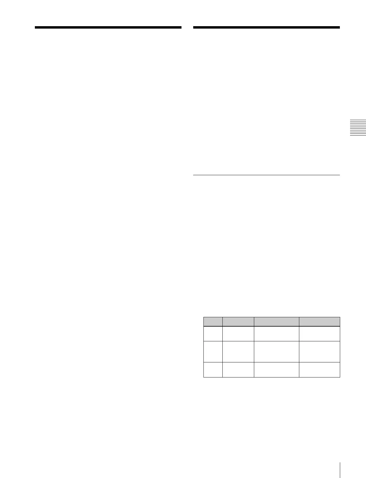
3
Set the source.
Source From: Specify the source start address for the
wiring configuration.
Source Level: Specify the source level for the wiring
configuration.
Knob Parameter Adjustment Setting values
1 Destination
(From)
Destination start
address
1 to 1024
2 Destination
(To)
Destination end
address
From start
address to
1024
3 Destination
(Level)
Destination level 1 to 8
 Loading...


