PGM-FI SYSTEM
4-24
DTC 8-2 (TP SENSOR HIGH VOLTAGE)
1. TP Sensor System Inspection
Turn the ignition switch
ON
and engine stop switch
"O".
Check the TP sensor with the
MCS
tester with the
throttle fully closed.
Is about 5 Vindicated?
YES -
GO
TO
STEP
3.
NO -
GO
TO
STEP
2.
2. TP Sensor Inspection
Check that
TP
sensor voltage
is
increasing
uninterrupted when moving the throttle from fully
closed
to
fully opened using the data list menu
of
the
MCS tester.
Does the voltage increase continuously?
YES -
Intermittent failure
NO -
Replace the sensor unit with a new one
and recheck (Faulty
TP
sensor).
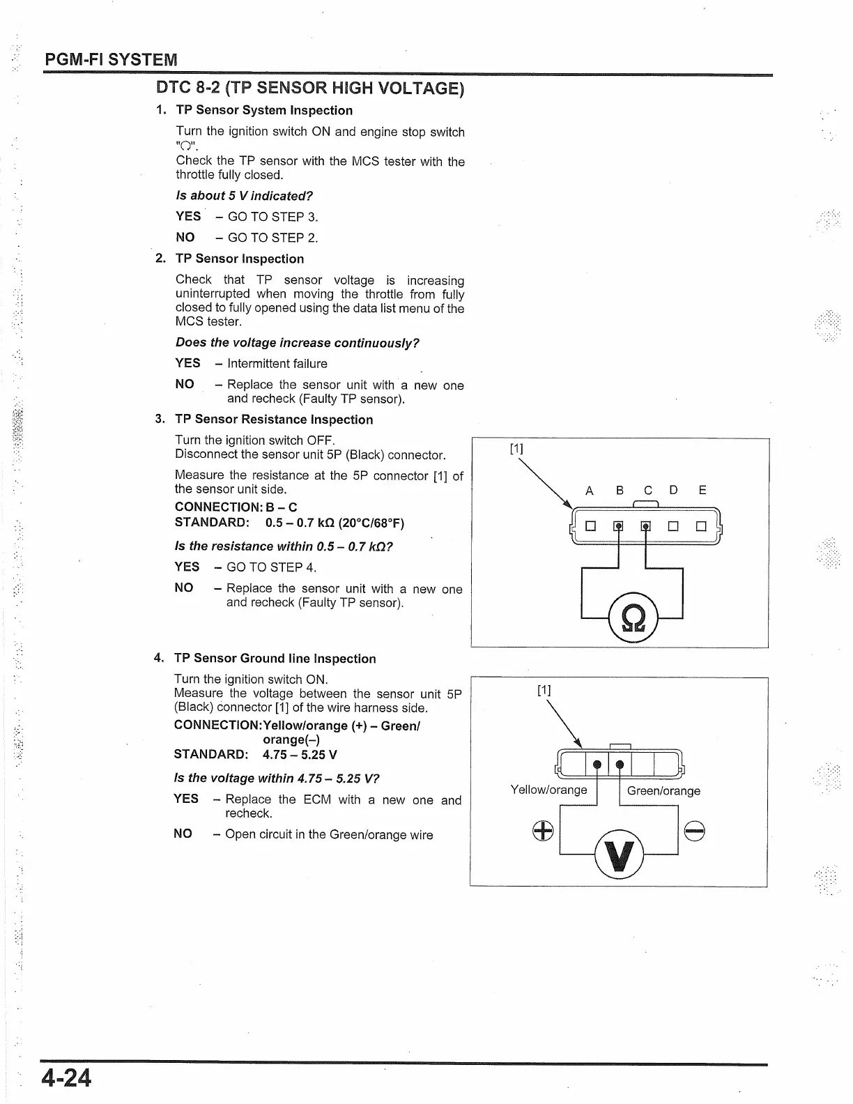
3. TP Sensor Resistance Inspection
Turn the ignition switch OFF.
Disconnect the sensor unit
SP
(Black) connector.
Measure the resistance at the
SP
connector
[1]
of
the sensor unit side.
CONNECTION:
B -
C
STANDARD:
0.5-
0.7 kO (20°C/68°F)
Is the resistance within 0.5 -
0.
7
k!l?
YES -
GO
TO
STEP
4.
NO -
Replace the sensor unit with a new one
and recheck (Faulty
TP
sensor).
4.
TP Sensor Ground line Inspection
Turn the ignition switch
ON.
Measure the voltage between the sensor unit
SP
(Black) connector
[1]
of the wire harness side.
CONNECTION:Yellow/orange
(+)-
Green/
orange(-)
STANDARD: 4.75 - 5.25 V
Is the voltage within
4.75-
5.25
V?
YES -
Replace the
ECM
with a new one and
recheck.
NO -
Open circuit
in
the Green/orange wire
B C D E
[1]
8
 Loading...