PGM-FI SYSTEM
4-40
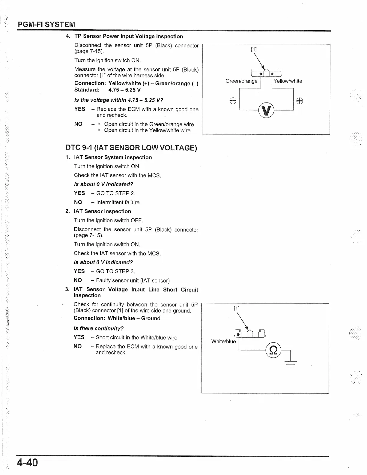
4. TP Sensor Power Input Voltage Inspection
Disconnect the sensor unit
5P
(Black) connector
(page 7-15).
Turn the ignition switch
ON.
Measure the voltage at the sensor unit
5P
(Black)
connector [1] of the wire harness side.
Connection: Yellow/white{+) - Green/orange{-)
Standard:
4.
75 - 5.25 V
Is the voltage within
4.75-
5.25
V?
YES -
Replace the ECM with a known good one
and recheck.
NO - •
Open circuit
in
the Green/orange wire
• Open circuit
in
the Yellow/white wire
DTC
9-1
(IAT SENSOR LOW VOLTAGE)
1.
IAT Sensor System Inspection
Turn the ignition switch
ON.
Check the IAT sensor with the MCS.
Is about O Vindicated?
YES -
GO
TO STEP
2.
NO -
Intermittent failure
2. IAT Sensor Inspection
Turn the ignition switch OFF.
Disconnect the sensor unit
5P
(Black) connector
(page 7-15).
Turn the ignition switch
ON.
Check the IAT sensor with the MCS.
Is
about O Vindicated?
YES -
GO
TO STEP
3.
NO -
Faulty sensor unit (IAT sensor)
3.
IAT Sensor Voltage Input Line Short Circuit
Inspection
Check for continuity between the sensor unit 5P
(Black) connector [1] of the wire side and ground.
Connection: White/blue - Ground
Is
there continuity?
YES -
Short circuit
in
the White/blue wire
NO -
Replace the
ECM
with a known good one
and recheck.
[1]
White/blue
 Loading...