INPUT
VOl
TAGE
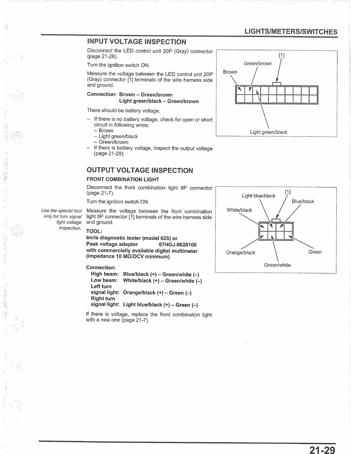
Disconnect the LED control unit 20P (Gray) connector
(page 21-28).
Turn the ignition switch
ON.
Measure the voltage between the LED control unit 20P
(Gray) connector
[1]
terminals
of
the wire harness side
and ground.
Connection: Brown - Green/brown
Light green/black - Green/brown
There should be battery voltage.
- If there
is
no
battery voltage, check for open or short
circuit
in
following wires:
- Brown
- Light green/black
- Green/brown
- If there
is
battery voltage, inspect the output voltage
(page 21-29).
OUTPUT
VOl
TAGE INSPECTION
FRONT COMBINATION LIGHT
Disconnect the front combination light
8P
connector
(page 21-7).
Turn the ignition switch
ON.
Use the special tool
Measure the voltage between the front combination
only for turn signal
light
8P
connector
[1]
terminals
of
the wire harness side
light voltage
and ground.
inspection.
TOOL:
Imrie diagnostic tester (model 625) or
Peak voltage adaptor O?HGJ-0020100
with commercially available digital multimeter
(impedance 10 MO/DCV
minimum_)
Connection:
High beam: Blue/black(+) - Green/white(-)
Low beam: White/black(+) - Green/white(-)
Left turn
signal light: Orange/black(+) - Green
(-)
Right turn
signal light: Light blue/black(+) - Green
(-)
If there
is
voltage, replace the front combination light
with a new one (page 21-7).
UGHTS/METERS/SWITCHES
[1]
Green/brown
Brown
Ir.
~11111111
Light green/black
 Loading...