PGM-FI SYSTEM
ECTSE
3.
ECM Power Line Inspection
Disconnect the ECM 33P (Black) connector (page
4-49).
Turn the ignition switch
ON.
Measure the voltage between the ECM 33P (Black)
connector [1] of the wire harness side and ground.
Connection: A24
(+) -
Ground
(-)
TOOL:
Test probe,
2
pack
07ZAJ-RDJA
110
Does the battery voltage exist?
YES - Replace the ECM with a known good one
and recheck.
NO - Open circuit
in
the Black/white wire
between the ignition switch and ECM.
REMOVAL/INSTALLATION
Remove the right side cover (page 2-8).
Drain the coolant (page 9-5).
Remove the
ECT
Disconnect the ECT sensor 2P (Black) connector [1]
sensor while the
from the sensor.
engine is cold.
Do not apply engine
Remove the ECT sensor
[2]
and replace the 0-ring
[3]
oil to this 0-ring.
with a new one.
Wear insulated
gloves and
adequate eye
protection.
Keep flammable
materials away from
the burner.
4-52
Tighten the ECT sensor
to
the specified torque.
TORQUE:
12 N·m (1.2 kgf·m, 9
lbMt)
Fill the cooling system with recommended coolant
(page 9-5).
Install the right side cover (page 2-8).
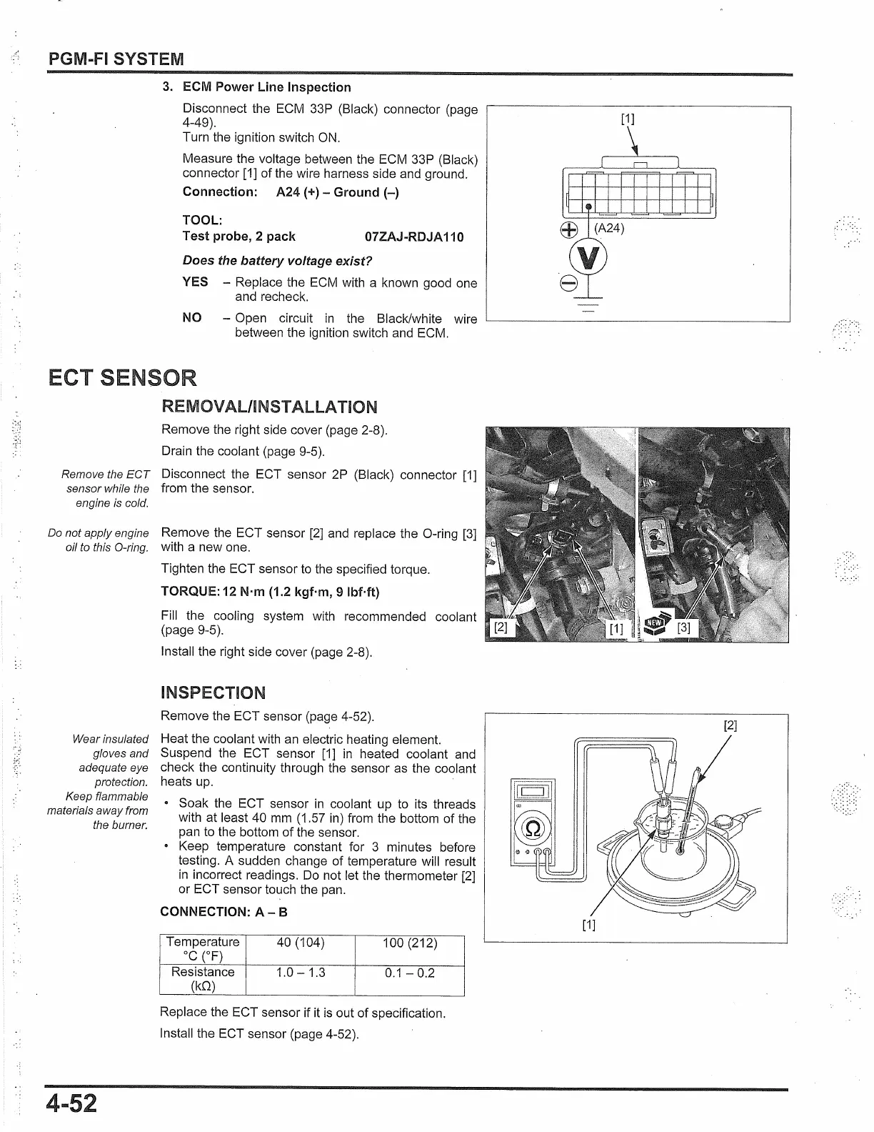
INSPECTION
Remove the ECT sensor (page 4-52).
Heat the coolant with an electric heating element.
Suspend the ECT sensor
[1]
in
heated coolant and
check the continuity through the sensor as the coolant
heats up.
Soak the ECT sensor
in
coolant up to its threads
with at least 40 mm (1.57 in) from the bottom of the
pan to the bottom
of
the sensor.
• Keep temperature constant for 3 minutes before
testing. A sudden change of temperature will result
in
incorrect readings.
Do
not let the thermometer
[2]
or ECT sensor touch the pan.
CONNECTION:
A-
B
Temperature
40 (104) 100 (212)
oc
(OF)
Resistance
1.0 - 1.3
0.1
-0.2
(kQ)
Replace the ECT sensor if
it
is
out of specification.
Install the ECT sensor (page 4-52).
[1]
[2]
[1]
 Loading...