···
..
'
...
~
. .
HIGH
NOTE:
Before starting the inspection, check for loose or poor
contact on the sensor unit 5P (Black) connector and
recheck the OTC.
1.
IAT Sensor System Inspection
Turn the ignition switch ON.
Check the IAT sensor with the MCS.
Is
about 5 Vindicated?
YES - GO TO STEP
2.
NO - • Intermittent failure
• Loose or poor contact on the sensor
unit
5P
(Black) connector
2.
Sensor Unit Power Line Inspection
Check the sensor unit power line inspection (page
4-33).
Is the sensor unit
power
line normal?
YES - GO TO STEP
3.
NO - Replace or repair the abnormal circuit.
3.
IAT Sensor Inspection
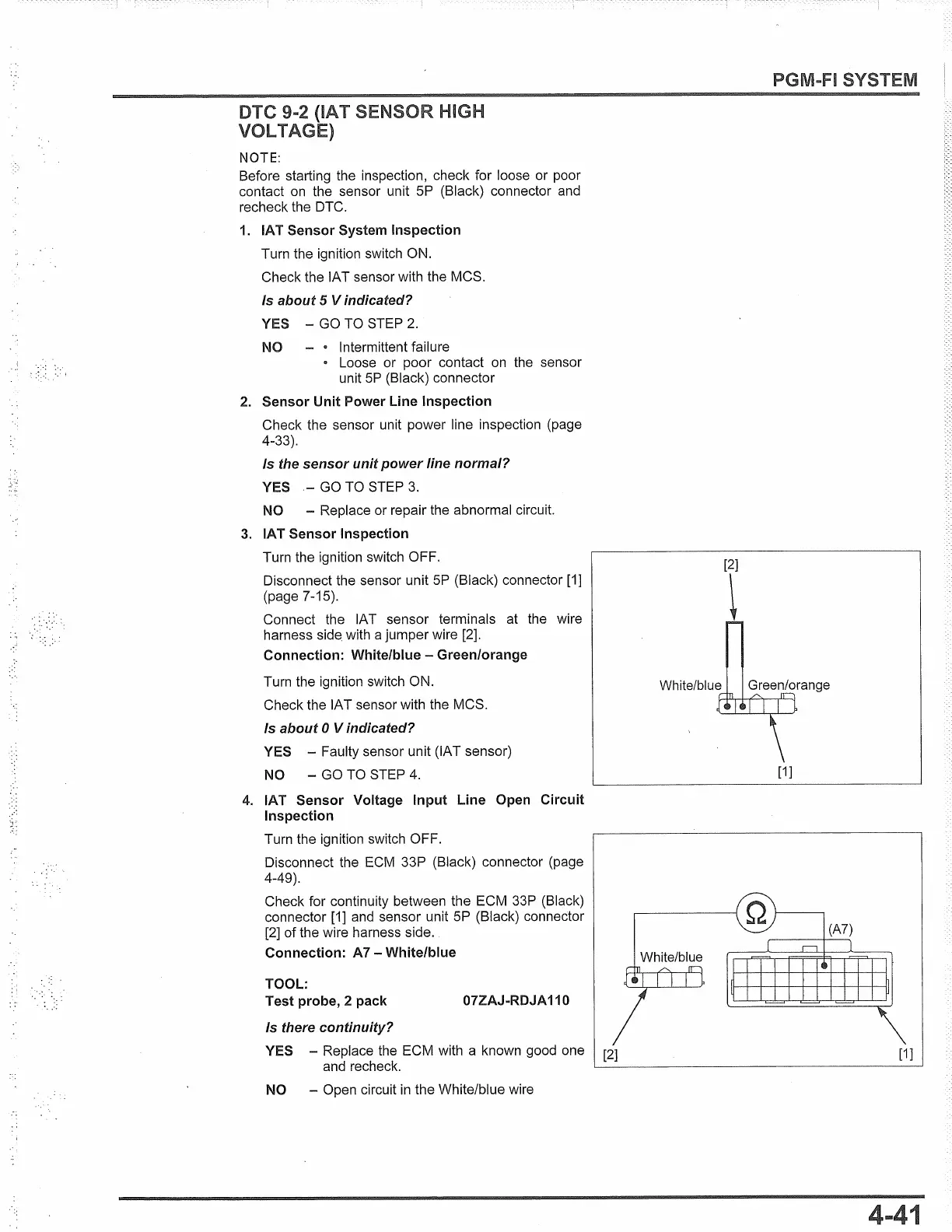
Turn the ignition switch OFF.
Disconnect the sensor unit 5P (Black) connector [1]
(page 7-15).
Connect the IAT sensor terminals at the wire
harness
side.
with a jumper wire
[2].
Connection: White/blue - Green/orange
Turn the ignition switch ON.
Check the IAT sensor with the MCS.
Is about O Vindicated?
YES - Faulty sensor unit (IAT sensor)
NO - GO TO STEP 4.
4.
IAT Sensor Voltage Input Line Open Circuit
Inspection
Turn the ignition switch OFF.
Disconnect the ECM 33P (Black) connector (page
4-49).
Check for continuity between the ECM 33P (Black)
connector [1] and sensor unit 5P (Black) connector
[2]
of
the wire harness side.
Connection: A7 - White/blue
TOOL:
Test probe, 2 pack 07ZAJ -RDJA 110
Is there continuity?
PGM-FI SYSTEM
[2]
~
White/blue Green/orange
[1]
White/blue
YES - Replace the ECM with a known good one [2]
[1]
and recheck.
'-------------------
NO - Open circuit in the White/blue wire
 Loading...