'.}
CYLINDER HEADNALVES
CAMS
Place a shop towel
at
the opening
of
the crankcase to
prevent the cam
sprocket bolt from
falling into the
crankcase.
10-8
REMOVAL
NOTE:
Camshaft
can
be
serviced with the engine installed
in
the frame.
Drain the coolant (page 9-5).
Drain the engine oil (page 3-12).
Remove the following:
- Body cover (page 2-23)
-
Th
rattle body (page 7 -15)
- Cylinder head cover (page 10-6)
- Water pump (page 9-8)
Set the piston
to
the TDC (Top
Dead
Center)
on
the
compression stroke (page 3-10).
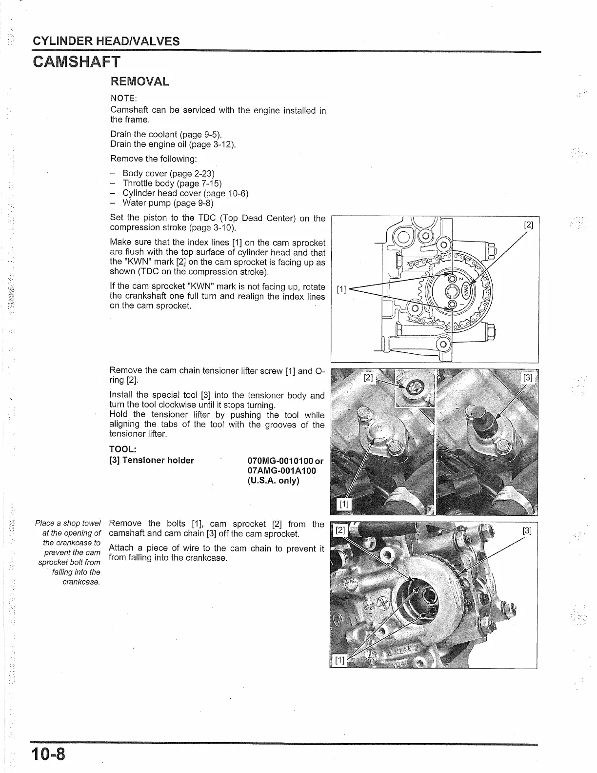
Make sure that the index lines
[1]
on
the
cam
sprocket
are flush with the top surface of cylinder head and that
the "KWN" mark
[2]
on
the
cam
sprocket
is
facing
up
as
shown (TDC
on
the compression stroke).
If the cam sprocket "KWN" mark
is
not facing
up,
rotate
the crankshaft one full turn and realign the index lines
on
the
cam
sprocket.
Remove the cam chain tensioner lifter screw
[1]
and
0-
ring [2].
Install the special tool
[3]
into the tensioner body and
turn the tool clockwise until it stops turning.
Hold the tensioner lifter by pushing the tool while
aligning the tabs of the tool with the grooves of the
tensioner lifter.
TOOL:
[3] Tensioner holder
070MG-0010100 or
07AMG-001A100
(U.S.A. only)
Remove the bolts
[1],
cam
sprocket
[2]
from the
camshaft and cam chain
[3]
off the
cam
sprocket.
Attach a piece of wire
to
the
cam
chain
to
prevent it
from falling into the crankcase.
 Loading...