LIGHTS/METERS/SWITCHES
COMBINATION M
MODEL)
R (AFTER '13
21-12
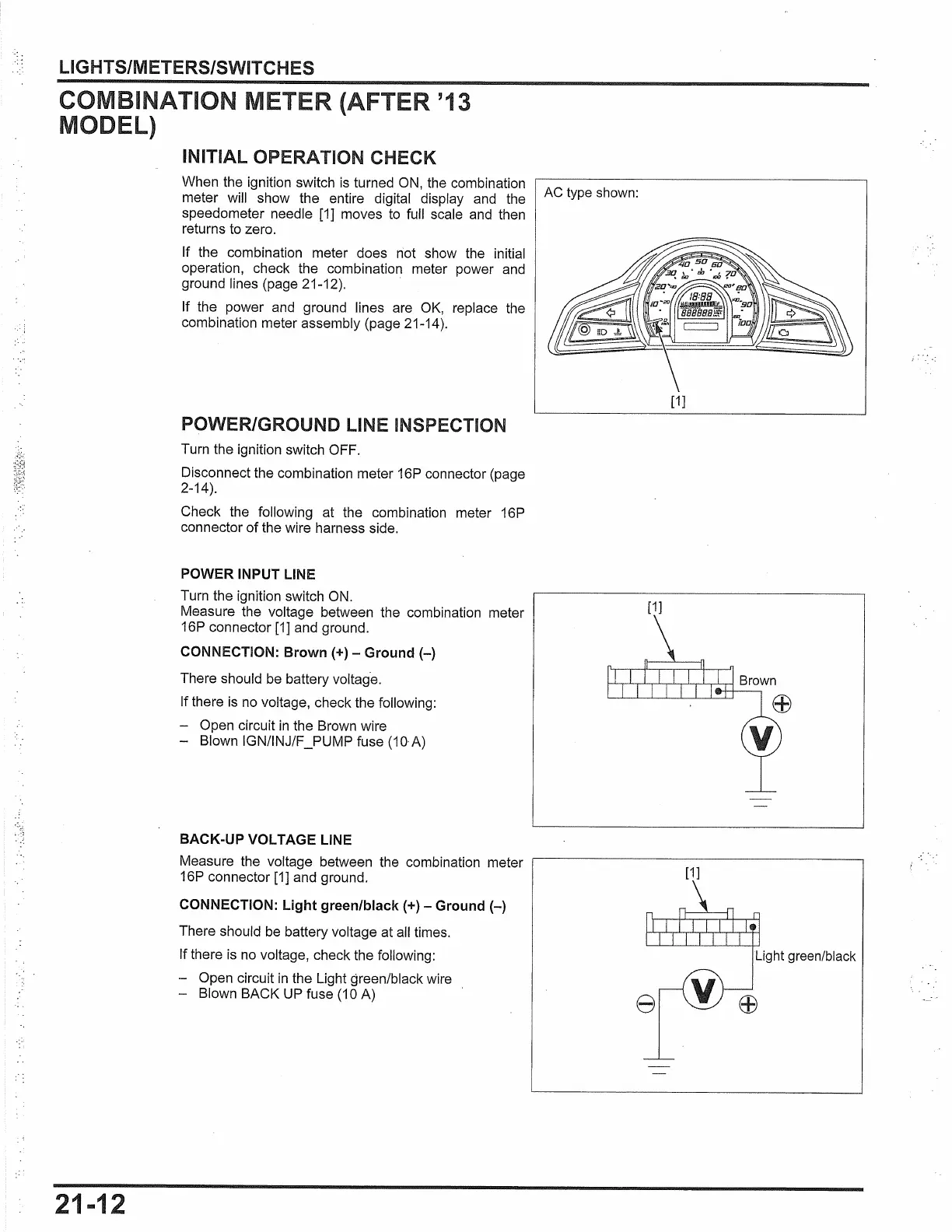
INITIAL OPERATION CHECK
When the ignition switch
is
turned
ON,
the combination
meter will show the entire digital display and the
speedometer needle [1] moves
to
full scale
and
then
returns to zero.
If the combination meter does riot show the initial
operation, check the combination meter power and
ground lines (page 21-12).
If the power and ground lines are
OK,
replace the
combination meter assembly (page 21-14).
POWER/GROUND LINE INSPECTION
Turn the ignition switch OFF.
Disconnect the combination meter 16P connector (page
2-14).
Check the following at the combination meter 16P
connector of the wire harness side.
POWER INPUT LINE
Turn the ignition switch
ON.
Measure the voltage between the combination meter
16P connector [1] and ground.
CONNECTION: Brown(+) - Ground
(-)
There should
be
battery voltag·e.
If there
is
no voltage, check the following:
- Open circuit
in
the Brown wire
- Blown IGN/INJ/F _PUMP fuse (10-A)
BACK-UP VOLTAGE LINE
Measure the voltage between the combination meter
16P connector [1] and ground.
CONNECTION:
light
green/black(+) - Ground
(-)
There should
be
battery voltage at
all
times.
If there
is
no
voltage, check the following:
- Open circuit
in
the Light green/black wire
- Blown BACK
UP
fuse (10 A)
AC
type shown:
[1]
[1]
[1]
Light green/black
8
 Loading...