SWITCH LINE INSPECTION
Disconnect the ECM SP connector (page 4-49).
Turn the ignition switch
ON
and
engine stop switch
"0".
Squeeze the rear brake lever and push the starter
switch.
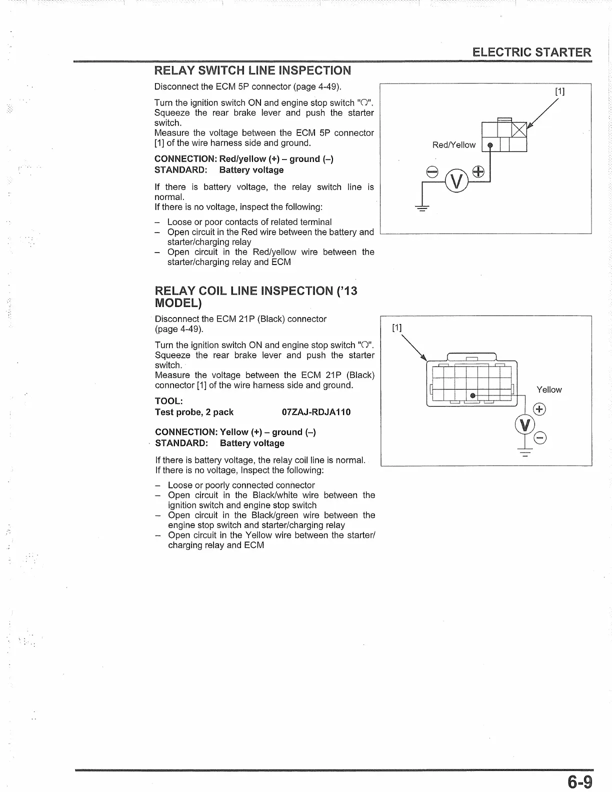
Measure the voltage between the
ECM
SP connector
[1]
of the wire harness side
and
ground.
CONNECTION:
Red/yellow(+)-
ground(-)
STANDARD: Battery voltage
If there
is
battery voltage, the relay switch line
is
normal.
If there
is
no
voltage, inspect the following:
- Loose or poor contacts of related terminal
- Open circuit
in
the Red wire between the battery and
starter/charging relay
- Open circuit
in
the Red/yellow wire between the
starter/charging relay and
ECM
RELAY COIL LINE INSPECTION ('13
MODEL)
Disconnect the ECM
21
P (Black) connector
(page 4-49).
Turn the ignition switch
ON
and
engine stop switch
"0".
Squeeze the rear brake lever and push the starter
switch.
Measure the voltage between the
ECM
21
P (Black)
connector
[1]
of the wire harness side and ground.
TOOL:
Test probe, 2 pack
07ZAJ-RDJA110
CONNECTION:
Yellow(+)-
ground(-)
STANDARD: Battery voltage
If there
is
battery voltage, the relay coil line
is
normal.
If there
is
no
voltage, Inspect the following:
- Loose or poorly connected connector
- Open circuit
in
the Black/white wire between the
ignition switch
and
engine stop switch
- Open circuit
in
the Black/green wire between the
engine stop switch and starter/charging relay
- Open circuit
in
the Yellow wire between the starter/
charging relay
and
ECM
[1]
Red/Yellow
 Loading...