1. Packets arrive at an incoming networking interface.
2. The networking interface passes the packets to the CFEB, where the integrated ASIC
processes the packet headers, divides the packets into 64-byte data cells, and
distributes the data cells throughout the memory buffer.
3. The integrated ASIC on the CFEB performs a route lookup for each packet and decides
how to forward it.
a. If services are configured for the packet, the integrated ASIC reassembles the
packet and passes it to the services interface.
b. The services interface passes the packet to the CFEB, where the integrated ASIC
processes the packet, divides the packet into 64-byte cells, and distributes the
data cells throughout the memory buffer.
c. The integrated ASIC performs a second route lookup for each packet and decides
how to forward it.
4. The integrated ASIC notifies the outbound networking interface.
5. The integrated ASIC reassembles data cells stored in shared memory into data packets
as they are ready for transmission and passes them to the outbound networking
interface.
6. The outbound networking interface transmits the data packets.
Related
Documentation
M10i Multiservice Edge Router Overview on page 8•
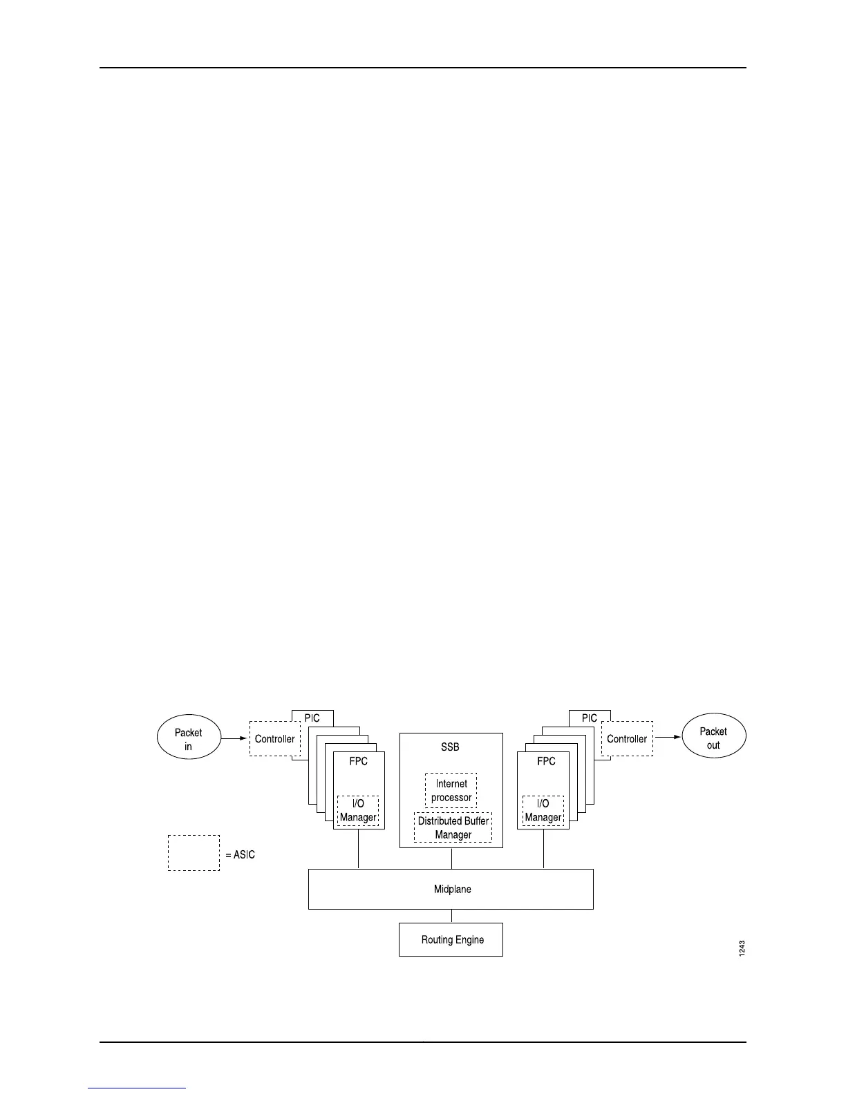
Data Flow Through the M20 Router Packet Forwarding Engine
Data flows through the M20 router Packet Forwarding Engine in the sequence shown in
Figure 26 on page 125 .
Figure 26: M20 Router Packet Forwarding Engine Components and Data
Flow
125Copyright © 2012, Juniper Networks, Inc.
Chapter 4: Monitoring Key Router Components

 Loading...


