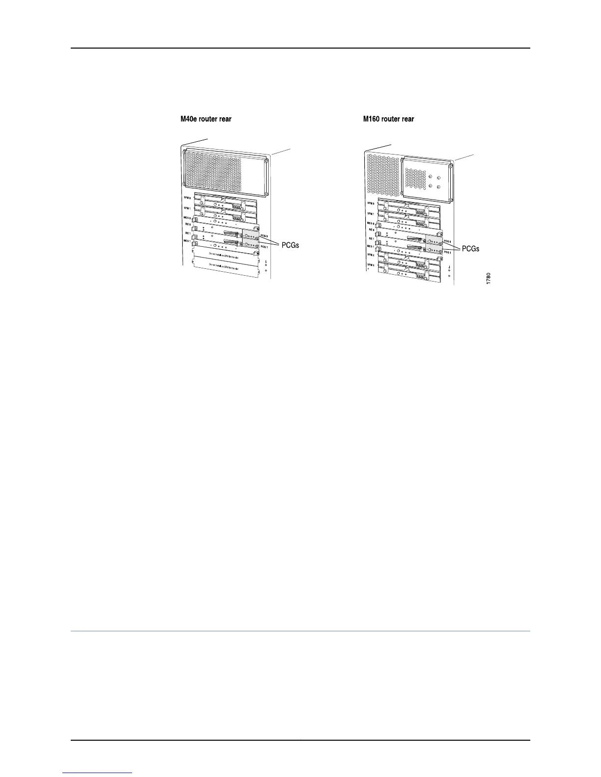
Figure 338: M40e and M160 Router PCG Location
During normal operation, both PCGs generate a 125-MHz clock signal to the Packet
Forwarding Engine modules, along with a signal indicating which is the master clock
source. One PCG is designated as the master. The master Routing Engine controls which
PCG is master and which is backup.
The modules and ASICs in the Packet Forwarding Engine that use the clock signal to gate
packet processing use only the signal from the master PCG.
The PCGs are field-replaceable and hot-pluggable. You can remove and replace them
without powering down the router, but the routing functions of the system are interrupted
when a PCG is removed.
If the master PCG fails or you remove it from the chassis, the Packet Forwarding Engine
resets so that the components start using the signal from the other PCG (which becomes
the master). Packet forwarding halts while there is no clock signal because the Packet
Forwarding Engine does not accept incoming packets. If the backup PCG fails or is
removed, router function is not affected.
Related
Documentation
Checklist for Monitoring Redundant PCGs on page 703•
Display Redundant PCG Hardware Information
Purpose To obtain information about the redundant PCG hardware.
Action To display redundant PCG hardware information, use the following command:
user@host> show chassis hardware
705Copyright © 2012, Juniper Networks, Inc.
Chapter 37: Monitoring Redundant PCGs

 Loading...


