1. Packets arrive at an incoming PIC interface.
2. The I/O Manager ASIC processes the packet headers, divides the packets into 64-byte
data cells, and passes the cells through the midplane to the SSB.
3. A Distributed Buffer Manager ASIC on the SSB distributes the data cells throughout
the memory buffers located on and shared by all the FPCs.
4. The Internet Processor II ASIC on the SSB performs a route lookup for each packet
and decides how to forward it.
5. The Internet Processor II ASIC notifies a Distributed Buffer Manager ASIC on the SSB
of the forwarding decision, and the Distributed Buffer Manager ASIC forwards the
notification to the FPC that hosts the appropriate outbound interface.
6. The I/O Manager ASIC on the FPC reassembles data cells stored in shared memory
into data packets as they are ready for transmission and passes them through the
Packet Director ASIC to the outbound PIC.
7. The outbound PIC transmits the data packets.
Related
Documentation
M20 Internet Router Overview on page 10•
Data Flow Through the M40 Router Packet Forwarding Engine
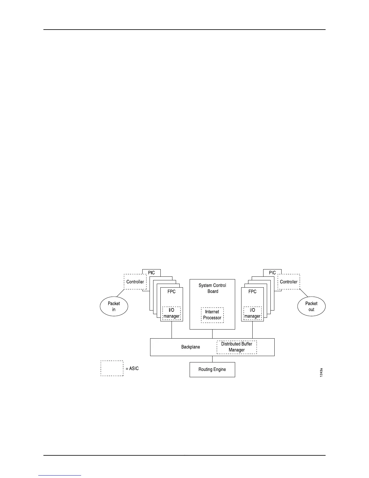
Data flows through the M40 router Packet Forwarding Engine in the sequence shown in
Figure 27 on page 126.
Figure 27: M40 Router Packet Forwarding Engine Components and Data
Flow
1. Packets arrive at an incoming PIC interface.
2. The PIC passes the packets to the FPC, where the I/O Manager ASIC processes the
packet headers, divides the packets into 64-byte data cells, and passes the cells to
the backplane.
Copyright © 2012, Juniper Networks, Inc.126
M Series and T Series Routers Monitoring and Troubleshooting Guide

 Loading...


