Amber . .
Green * *
Blue * .
[...Output truncated...]
Meaning The command output is for an M160 router. The PCGs in slots 0 and 1 are online and are
functioning normally. The status colors represent the possible PCG operating states:
Amber (Fail), Green (OK), and Blue (Master). The (*) indicates the current operating
state.
Check the PCG LED States on the Faceplate
Purpose To obtain PCG LED states on the PCG faceplate.
Action To view the PCG LEDs, remove the rear component cover and look on the PCG faceplate
at the rear of the M40e or M160 router chassis (see “PCG Overview” on page 467). Table
120 on page 470 describes the functions of these LEDs.
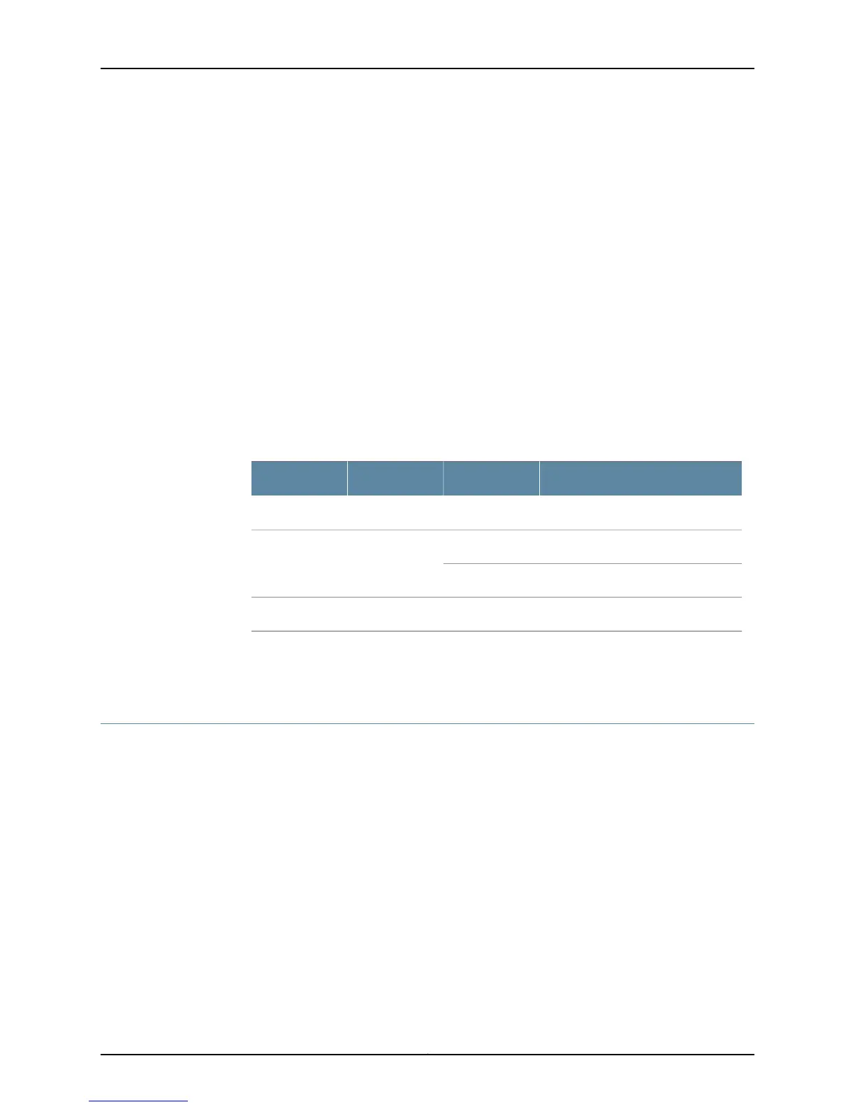
Table 120: PCG LEDs
DescriptionStateLabelColor
PCG is master.On steadilyMASTERBlue
PCG is operating normally.On steadilyOKGreen
PCG is starting up.Blinking
PCG has failed.On steadilyFAILAmber
Related
Documentation
Checklist for Monitoring the PCG on page 465•
Determine PCG Mastership
The PCGs function as redundant components. For information about monitoring
redundant PCGs, see “Checklist for Monitoring Redundant PCGs” on page 703.
To determine which PCG is operating as the master:
1.
Display the PCG Master in the Craft Interface Output on page 470
2.
Check the PCG LED States for PCG Mastership on the Faceplate on page 471
3.
Display the Packet Forwarding Engine Current Clock Source on page 471
Display the PCG Master in the Craft Interface Output
Purpose To display the PCG master in the craft interface output.
Action To determine the PCG master from the craft interface status information, use the following
command:
Copyright © 2012, Juniper Networks, Inc.470
M Series and T Series Routers Monitoring and Troubleshooting Guide

 Loading...


