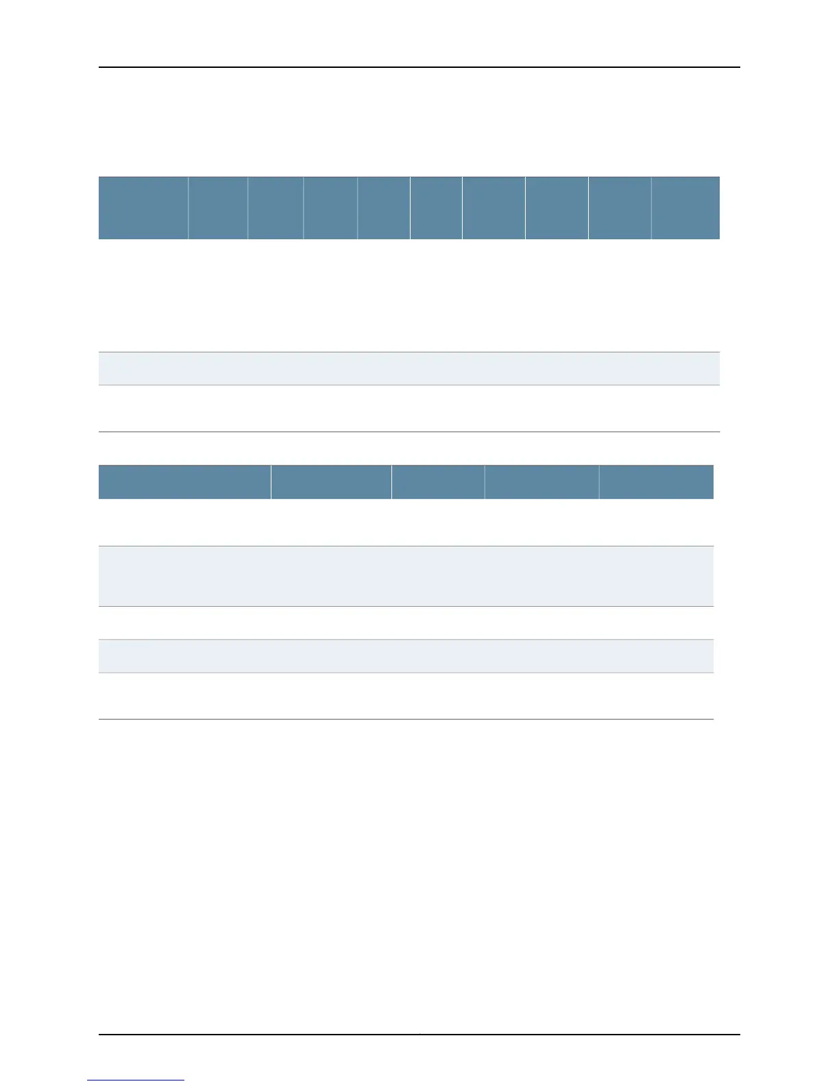
Table 143: M Series Router Redundant Cooling System Components Characteristics
(continued)
M320M160M120M40eM40M20M10iM7i
M5 and
M10
Cooling
System
Component
_1 upper
2 rear
_1 central
1 rear
upper
1 rear
lower
2 pairs____Impellers
____3____Fan assemblies
1 front
1 rear
1111____Air filter
Table 144: T Series Routers Redundant Cooling System Components Characteristics
TX Matrix PlusTX MatrixT1600T320/T640/Cooling System Component
2 front
4 rear
2 front
1 rear
2 front
1 rear
2 front
1 rear
Fan tray
Cooled by air
flowing through the
chassis
Cooled by air
flowing through the
chassis
Cooled by air
flowing through
the chassis
Cooled by air flowing
through the chassis
Power supply integrated fan
____Impellers
____Fan assemblies
3 front1 front
1 rear
1 front
1 rear
1 front
1 rear
Air filter
Related
Documentation
Checklist for Monitoring Redundant Cooling System Components on page 623•
M5 and M10 Router Redundant Cooling System Components
The M5 and M10 router cooling system consists of a fan tray containing four fans that
inserts into the left side of the chassis (left fans 1 through 4). The fan tray connects to
the router midplane and provides side-to-side cooling. (See Figure 309 on page 626.)
The fan tray is hot-removable and hot-insertable. You can remove and replace these
components without powering down the system and disrupting routing functions.
The cooling system is fault-tolerant. The router can tolerate the failure of a single fan for
approximately 36 hours. If a fan fails, the router issues a yellow alarm and the yellow
625Copyright © 2012, Juniper Networks, Inc.
Chapter 31: Monitoring Redundant Cooling System Components

 Loading...


