to the odd side of the TXP-F13 SIBs in slots 8 through 15 are routed to the lower right
cable management arm, and the cables connected to the even side are routed to the
lower left cable management arm.
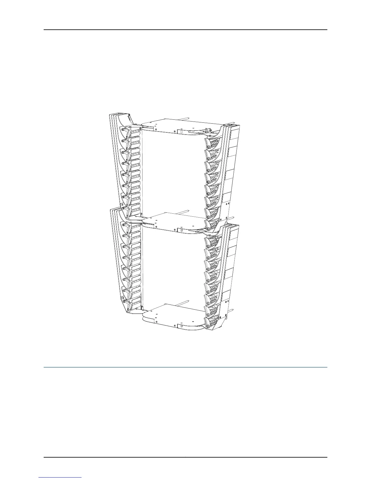
Figure 190 on page 359 shows the TX Matrix Plus cable management system.
Figure 190: TX Matrix Plus Rear Cable Management System
Related
Documentation
Checklist for Maintaining Cables and Connectors on page 351•
Maintaining the PIC Cables
To maintain the PIC cables, follow these guidelines:
•
Make sure that you use the cable and connector type that is specified in the appropriate
router hardware guide, especially for the cable and connectors that are not supplied,
such as the single-mode interface (fiber) and multimode interface (fiber).
•
Make sure that all cable connectors are securely connected. Securely screw in the
cable connector screws.
359Copyright © 2012, Juniper Networks, Inc.
Chapter 12: Maintaining the Cable Management System, Cables, and Connectors

 Loading...


