PCG Overview
You monitor the PCGs to ensure that they generate a clock signal to synchronize the
modules and application-specific integrated circuits (ASICs) that make up the Packet
Forwarding Engine.
The PCG supplies a 125-MHz system clock to synchronize the modules and ASICs that
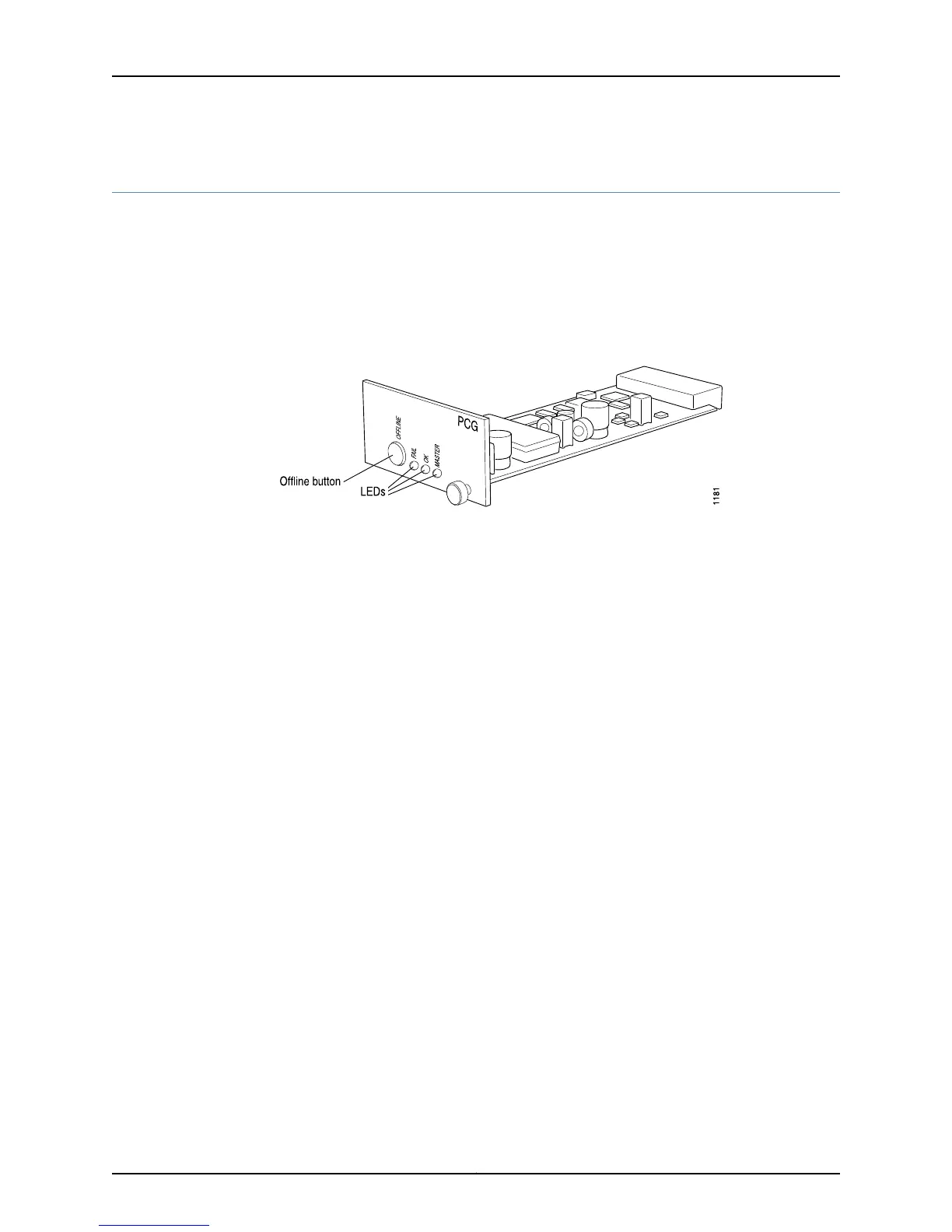
make up the Packet Forwarding Engine (see Figure 251 on page 467).
Figure 251: PCG Component
A router has two PCGs. They are located at the rear of the chassis in the slots labeled
PCG0 and PCG1, to the right of the Routing Engine slots.
Both PCGs send clock signals to the Packet Forwarding Engine modules, along with a
signal indicating which is the master clock source. The master Routing Engine controls
which PCG is master and which is backup.
The PCGs are field-replaceable and hot-pluggable. You can remove and replace them
without powering down the router; however, the routing functions of the system are
interrupted when a PCG is removed.
Removing the backup PCG does not affect the functioning of the router. Taking the master
PCG offline causes the Flexible PIC Concentrators (FPCs) and Switching and Forwarding
Modules (SFMs) to power down and restart with the other PCG selected as master. The
forwarding and routing functions are interrupted during this process.
Figure 252 on page 468 shows the location of the PCGs on the M40e and M160 router
chassis.
467Copyright © 2012, Juniper Networks, Inc.
Chapter 20: Monitoring the PCG

 Loading...


