Home
Juniper
Network Router
M Series
Juniper M Series User Manual
5
of 1
of 1 rating
812 pages
Give review
Manual
Specs
To Next Page
To Next Page
To Previous Page
To Previous Page
Loading...
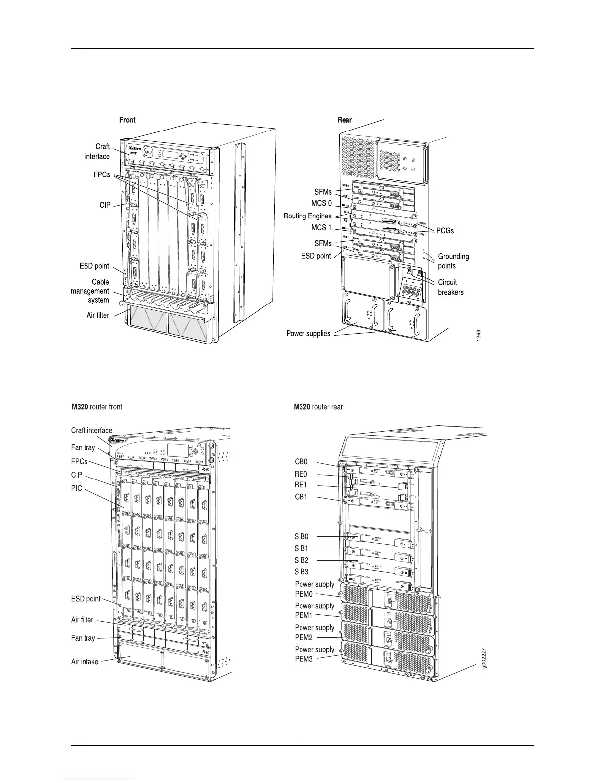
Figure
43:
M160
R
outer
Chassis
and
Components
Figure
44
on
p
age
147
sho
ws
the
front
and
re
ar
of
the
M320
Internet
r
outer
chassis
and
the
install
ed
components.
Figure
44:
M320
R
outer
Chassis
and
Component
s
14
7
Copyright
©
2012,
Juniper
Net
works,
Inc.
Chapter
5:
Monit
oring
the
Rout
er
Chassis
190
192
Table of Contents
Default Chapter
1
Series and T Series Routers
1
Table of Contents
3
About the Documentation
39
Junos Documentation and Release Notes
39
Objectives
39
Audience
40
Supported Routing Platforms
40
About the Documentation
41
Document Conventions
41
Table 1: Notice Icons
41
Table 2: Text and Syntax Conventions
41
Using the Index
41
Documentation Feedback
42
Requesting Technical Support
43
Self-Help Online Tools and Resources
43
Opening a Case with JTAC
43
Juniper Networks M Series and T Series Routers
45
M Series Multiservice Edge Routers
45
T Series Core Routers
45
Chapter 1 M Series Multiservice Edge Routers
47
M5 and M10 Internet Router Overview
48
Figure 1: M5 and M10 Routers
48
M5 and M10 Router Components
49
Table 3: M5 and M10 Router Major Hardware Components
49
M7I Multiservice Edge Router Overview
50
Figure 2: M7I Router
50
M7I Router Components
51
Table 4: M7I Router Major Hardware Components
51
M10I Multiservice Edge Router Overview
52
Figure 3: M10I Router
52
M10I Router Components
53
Table 5: M10I Router Major Hardware Components
53
M20 Internet Router Overview
54
M20 Router Components
55
Figure 4: M20 Router
55
Table 6: M20 Router Major Hardware Components
56
M40 Router Overview
57
Figure 5: M40 Router
57
M40 Router Components
58
Table 7: M40 Router Major Hardware Components
58
M40E Multiservice Edge Router Overview
59
Figure 6: M40E Router
59
M40E Router Major Hardware Components
60
Table 8: M40E Router Major Hardware Components
60
M120 Multiservice Edge Router Overview
61
Figure 7: Front View of an M120 Router
61
Figure 8: Rear View of an AC M120 Router
62
M120 Router Major Hardware Components
63
Figure 9: Rear View of a DC M120 Router
63
Table 9: M120 Router Major Hardware Components
63
M160 Internet Router Overview
65
Figure 10: M160 Router
65
M160 Router Major Hardware Components
66
Table 10: M160 Router Major Hardware Components
66
M320 Multiservice Edge Router Overview
67
M320 Router Major Hardware Components
68
Figure 11: M320 Router
68
Table 11: M320 Router Major Hardware Components
69
Chapter 2 T Series Core Routers
71
T320 Core Router Overview
71
Figure 12: Front View of the T320 Router
72
Figure 13: Rear View of the T320 Router
73
T Series Core Routers
73
T320 Router Major Hardware Components
74
Table 12: T320 Router Major Hardware Components
74
T640 Core Router Overview
75
Figure 14: T640 Router
76
T640 Router Major Hardware Components
77
Table 13: T640 Router Major Hardware Components
77
T1600 Core Router Overview
78
Figure 15: Front View of the T1600 Router
79
Figure 16: Rear View of the T1600 Router
80
T1600 Router Major Hardware Components
81
Table 14: T1600 Router Major Hardware Components
82
TX Matrix Router Overview
83
Figure 17: Front View of a TX Matrix Router
84
Figure 18: Rear View of a TX Matrix Router
85
TX Matrix Router Major Hardware Components
86
Table 15: TX Matrix Router Major Hardware Components
86
TX Matrix Plus Router Overview
87
Figure 19: Front View of a TX Matrix Plus Router
88
TX Matrix Plus Router Major Hardware Components
89
Figure 20: Rear View of a TX Matrix Plus Router
89
Table 16: TX Matrix Plus Router Major Hardware Components
89
Methodology and Tools for Monitoring Router Components
93
Method and Tools for Monitoring Router Components
93
Chapter 3 Method and Tools for Monitoring Router Components
95
Basic Router Component Monitoring Method
95
Figure 21: Basic Method for Monitoring Router Components
95
Basic Router Component Monitoring Tools
96
Table 17: Basic Tools for Monitoring Router Components
96
Common Operational Mode Commands to Monitor Router Components
100
Table 18: Operational Mode Commands for Router Monitoring
101
Using the Basic Monitoring Method
103
Check the Router Component Status
104
Check the Router Craft Interface
104
Table 19: Show Chassis Craft-Interface Command Output for Router Types
104
Table 20: M Series Router Craft Interface Component Characteristics
105
Table 21: T Series Router Craft Interface Component Characteristics
106
Check the Component Leds
107
Table 22: Component LED Location on the Router
108
Display Detailed Component Environmental Information
109
Display Detailed Component Operational Information
110
Table 23: Component Detailed Environmental Status Commands
110
Gather Component Alarm Information
111
Display the Current Router Alarms
111
Table 24: Component Detailed Operational Status Commands
111
Table 25: M5 or M10 Router Chassis Component Alarm Conditions
112
Table 26: M7I or M10I Router Chassis Component Alarm Conditions
115
Table 27: M20 Router Chassis Component Alarm Conditions
118
Table 28: M40 Router Chassis Component Alarm Conditions
120
Table 29: M40E or M160 Router Chassis Component Alarm Conditions
124
Table 30: M120 Router Chassis Component Alarm Conditions
130
Table 31: M320 Router Chassis Component Alarm Conditions
133
Table 32: T320 Router Chassis Component Alarm Conditions
137
Table 33: T640 Router Chassis Component Alarm Conditions
141
Table 34: T1600 Router Chassis Component Alarm Conditions
146
Table 35: TX Matrix and TX Matrix Plus Router Chassis Component Alarm
152
Display Error Messages in the Messages Log File
156
Display Error Messages in the Chassis Daemon Log File
157
Verify the Component Problem
158
Fix the Problem
158
Contact JTAC
159
Return the Failed Component
160
Monitoring Key and Common Router Components
161
Monitoring Key Router Components
161
Chapter 4 Monitoring Key Router Components
163
Understanding Key Router Components
163
Packet Forwarding Engine
164
Figure 22: Router Architecture
164
Table 36: Packet Forwarding Engine Forwarding Rate and Aggregate Throughput Characteristics Per Routing Platform
164
Table 37: Router Packet Forwarding Engine Components Per Routing
165
Data Flow through the Router Packet Forwarding Engine
166
Data Flow through the M5 and M10 Router Packet Forwarding Engine
166
Figure 23: M5 and M10 Router Packet Forwarding Engine Components and Data Flow
166
Data Flow through the M7I Router Packet Forwarding Engine
167
Figure 24: M7I Router Packet Forwarding Engine Components and Data Flow
167
Data Flow through the M10I Router Packet Forwarding Engine
168
Figure 25: M10I Router Packet Forwarding Engine Components and Data
168
Data Flow through the M20 Router Packet Forwarding Engine
169
Figure 26: M20 Router Packet Forwarding Engine Components and Data
169
Data Flow through the M40 Router Packet Forwarding Engine
170
Data Flow through the M40E Router Packet Forwarding Engine
171
Data Flow through the M120 Router Packet Forwarding Engine
172
Data Flow through the M160 Router Packet Forwarding Engine
172
Data Flow through the M320 Router Packet Forwarding Engine
173
Engine
174
Figure 30: M320 Router Packet Forwarding Engine Components and Data
174
Figure 31: T320, T640, and T1600 Router Packet Forwarding Engine Components
176
Data Flow through the TX Matrix Router Packet Forwarding Engine
177
Figure 32: TX Matrix Router Packet Forwarding Engine Components and Data
178
Data Flow through the TX Matrix Plus Router Packet Forwarding Engine
179
Figure 33: TX Matrix Plus Router Packet Forwarding Engine Components and
180
Routing Engine
181
Routing Engine Functions
182
Figure 34: Routing Engine Architecture
182
Figure 35: Control Packet Handling for Routing and Forwarding Table
183
Table 38: Checklist for Monitoring the Router Chassis
185
Chapter 5 Monitoringtherouterchassis
186
Router Chassis Overview
186
Figure 36: M5 and M10 Router Chassis and Components
187
Figure 37: M7I Router Chassis and Components
187
Figure 38: M10I Router Chassis and Components
188
Figure 39: M20 Router Chassis and Components
188
Figure 40: M40 Router Chassis and Components
189
Figure 41: M40E Router Chassis and Components
189
Figure 42: M120 Router Chassis and Components
190
Figure 43: M160 Router Chassis and Components
191
Figure 44: M320 Router Chassis and Components
191
Figure 45: Front View of the T320 Router
192
Figure 46: Front View of the T320 Router
193
Figure 47: T640 Router and Components
194
Figure 48: Front View of the T1600 Router
195
Figure 49: Rear View of the T1600 Router
196
Figure 50: Front View of the TX Matrix Router
197
Figure 51: Rear View of the TX Matrix Router
198
Figure 52: Front View of the TX Matrix Plus Router
199
Figure 53: Rear View of the TX Matrix Plus Router
200
Check the Router Chassis Component Status
200
Display the Hardware Components Installed in the Router Chassis
200
Check the Component Environmental Status
201
Check the Component Status from the Craft Interface
202
Check Router Alarms
203
Display Component Error Messages in the System Log File
205
Display Component Errors in the Chassis Daemon Log File
205
Verify Router Component Failure
206
Replace a Failed Component
206
Table 39: Checklist for Monitoring the Routing Engine
209
Chapter 6 Monitoringtheroutingengine
212
Understanding the Routing Engine
212
Routing Engine Types and Characteristics
213
Table 40: Routing Engine Characteristics Per Routing Platform
213
Figure 54: M7I and M10I Router Routing Engine
214
Figure 55: M5, M10, M20, M40, M40E, M120 and M160 Router Routing
214
Figure 56: M320 Router Routing Engine
215
Figure 57: T320, T640, T1600, and TX Matrix Router Routing Engine
215
Figure 58: TX Matrix Plus Router Routing Engine
216
Routing Engine Locations
216
Figure 59: M5, M10, and M20 Router Routing Engine Location
216
Figure 60: M7I and M10I Router Routing Engine Location
217
Figure 61: M40 Router Routing Engine Location
217
Figure 62: M40E and M160 Router Routing Engine Location
218
Figure 63: M120 Routing Engine Location
219
Figure 64: M320 Router Routing Engine Location
219
Figure 65: T320, T640, and T1600 Routing Engine Location
220
Routing Engine Redundancy
220
Table 41: Redundant Routing Engines
221
Monitor the Routing Engine Status
222
Check the Detailed Routing Engine Status
223
Check the Routing Engine Leds
224
Check the M7I Routing Engine Leds
224
Figure 66: M10I Routing Engine Leds
225
Table 42: M7I Router Routing Engine LED States
225
Check the M10I Router Routing Engine Leds
225
Table 43: M10I Router Routing Engine Leds and Buttons
225
Check the M20 Router Routing Engine Leds
226
Figure 67: M20 Router Craft Interface Routing Engine Leds and Buttons
226
Table 44: M20 Router Routing Engine Leds and Buttons
226
Figure 68: M20 Router Routing Engine Panel
227
Table 45: Routing Engine Panel Leds
227
Check the M40 Router Routing Engine Leds
227
Figure 69: M40 Routing Engine Panel
228
Table 46: M40 Router Routing Engine Leds
228
Check the M120 Router Routing Engine Leds
228
Figure 70: Front Panel of the M120 Craft Interface
229
Figure 71: M40E and M160 Router Redundant Host Module Leds
229
Table 47: M120 Routing Engine LED
229
Figure 72: M320 Router Redundant Host Module Leds
230
Check the M320 Router Routing Engine Leds
230
Table 48: M40E and M160 Router Host Module Leds
230
Table 49: M320 Router Host Subsystem Leds
230
Figure 73: T320 Router Redundant Host Module Leds
231
Table 50: T320 Router Host Subsystem Leds
231
Figure 74: T640 Router Redundant Host Module Leds
232
Figure 75: T1600 Router Redundant Host Module Leds
232
Check the T1600 Router Routing Engine Leds
232
Table 51: T640 Router Host Subsystem Leds
232
Figure 76: TX Matrix Router Redundant Host Module Leds
233
Check the Tx Matrix Router Routing Engine Leds
233
Table 52: T1600 Router Host Subsystem Leds
233
Table 53: TX Matrix Router Host Subsystem Leds
233
Check the Tx Matrix Plus Router Routing Engine Leds
234
Figure 77: TX Matrix Plus Router Routing Engine RE-C2600 Leds
234
Table 54: TX Matrix Plus Routing Engine RE-C2600 Leds
234
Verify Routing Engine Failure
239
Check Core Files if the Routing Engine Reboots
240
List the Core Files Generated after a Crash Occurs
240
Display the Messages Log File after a Crash Occurs
240
Display the Log File When Kernel Crash Core File Is Not Generated
241
Check for Compactflash Card and Hard Disk Failure
241
When the Compactflash Card Is Removed from the Boot List
242
Determine Why Compactflash Card DID Not Mount
242
When the Hard Disk Is Removed from the Boot List
243
Verify that the Hard Disk DID Not Mount
243
Verify that the Hard Disk Is Missing from the Boot List
244
View Alarms When Media Is Removed from the Boot List
244
Understand What Happens When Memory Failures Occur
245
Check the Router File System and Boot Disk
245
Table 55: Storage Media Device Names
245
Display the Current Routing Engine Alarms
246
Display Error Messages in the System Log File
247
Document the Events Prior to the Failure
247
Display Routing Engine Hardware Information
248
Locate the Routing Engine Serial Number ID Label
248
Figure 78: M10I Router Routing Engine Serial Number ID Label Location
249
Figure 79: Routing Engine Serial Number ID Label Location for All Routers
250
M40 Router Routing Engine Serial Number ID Label Location
250
Figure 80: M40 Router Routing Engine Serial Number ID Label
251
Figure 81: M120 Routing Engine Serial Number Label
251
Figure 82: M320 Router Routing Engine Serial Number ID Label Location
252
Figure 83: T320 Router and T640 Router Routing Engine Serial Number ID
252
Figure 84: T1600 Router Routing Engine Serial Number ID Label
253
Figure 85: TX Matrix Router Routing Engine Serial Number ID Label Location
254
Figure 86: TX Matrix Plus Router Routing Engine Serial Number ID Label
254
Removing a Routing Engine
255
Table 56: Checklist for Monitoring Fpcs
257
Chapter 7 Monitoringfpcs
259
Understanding Fpcs
259
Table 57: FPC Characteristics Per Routing Platform
259
Figure 87: FPC Numbering
260
Checking the Fpc Status
260
Check Fpc Status and Uptime
261
Checking Fpc Status and Temperature
262
Checking Fpc Status and Temperature in a T1600 Router
262
Checking the Fpc Led States
263
Table 58: FPC Leds on the Faceplate
264
Table 59: FPC Leds on the Craft Interface
264
Checking for Fpc Alarms
264
Replacing an Fpc
264
Displaying Fpc Error Messages in the System Log File
265
Displaying Fpc Error Messages in the Chassis Daemon Log File
266
Verifying Fpc Failure
268
Document Events Prior to the Fpc Failure
268
Checking the Fpc Installation
269
Checking the Fpc Fuses
269
Figure 88: Component Fuses in the M320 Router Midplane
270
Display the Fpc Hardware Information
272
Locating the Fpc Serial Number ID Label
272
Figure 89: M20 Router FPC Serial Number ID Label
273
Figure 90: M40 Router FPC Serial Number ID Label
273
Figure 91: M40E and M160 Router FPC Serial Number ID Label
274
Figure 92: M120 FPC Serial Number Label
274
Figure 93: M320 FPC Serial Number ID Label
275
Figure 94: T320 Router FPC Serial Number ID Label
276
Figure 95: T640 Router FPC Serial Number Label
277
Figure 96: T1600 Router FPC Serial Number Label
278
Replace the Fpc
278
Table 60: Checklist for Monitoring Pics
279
Chapter 8 Monitoringpics
280
Pics Overview
280
Table 61: PIC Characteristics Per Routing Platform
280
Figure 97: PIC Location, Row, and Slot Numbering
282
Checking the Pic Status
283
Display the Pic Media Type and Fpc Status
283
Display the Pic Interface Status Information
284
Table 62: Tunnel PIC Leds
285
Viewing the Pic Led States
285
Checking Pic Alarms
286
Checking the Current Chassis Alarms
286
Display the Error Messages in the System Log File
286
Verifying Pic Failure
287
Performing a Pic Swap Test
287
Displaying the Pic Hardware Information
288
Locating the Pic Serial Number ID Label
288
Figure 98: PIC Serial Number ID Label (Horizontal Orientation)
289
Figure 99: PIC Serial Number ID Label (Vertical Orientation)
289
Figure 100: M320 Router Serial Number ID Label on PIC
290
Figure 101: T320 Router Serial Number ID Label on PIC
290
Figure 102: T640 and T1600 Router Serial Number Label on PIC
291
Chapter 9 Monitoring the Craft Interface
293
Checklist for Monitoring the Craft Interface
293
Table 63: Checklist for Monitoring the Craft Interface
294
Figure 103: M5 and M10 Router Craft Interface
296
Figure 104: M20 Router Craft Interface
296
Understanding the Craft Interface
296
Figure 105: M40 Router Craft Interface
297
Figure 106: M40E and M160 Router Craft Interface
297
Figure 107: M120 Router Craft Interface
297
Figure 108: M320 Router Craft Interface
298
Figure 109: T320, T640 and T1600 Router Craft Interface
298
Figure 110: TX Matrix Router Craft Interface
298
Figure 111: TX Matrix Plus Router Craft Interface
299
Table 64: Router Craft Interface Characteristics Per Routing Platform
299
Monitoring the Craft Interface Status
300
Viewing Craft Interface Information from the Command Line
302
Verifying Craft Interface Failure
303
Display Craft Interface Error Messages in the System Log File
304
Displaying Craft Interface Messages in the Chassis Daemon Log File
304
Displaying Craft Interface Hardware Information
305
Replacing the Craft Interface
306
Figure 112: Removing the Lower Impeller Tray
307
Figure 113: Removing the Front Upper Impeller Assembly
307
Figure 114: Removing the M120 Craft Interface
308
Figure 115: Removing the M320 Router Craft Interface
309
Figure 116: Removing the TX Matrix Router Craft Interface
310
Figure 117: Removing the TX Matrix Plus Router Craft Interface
311
Locating the Craft Interface Serial Number ID Label
311
Figure 118: M20 Router Craft Interface Serial Number ID Label
312
Figure 119: M40 Router Craft Interface Serial Number ID Label
312
Figure 120: M40E and M160 Router Craft Interface Serial Number ID Label
313
Figure 121: M120 Router Craft Interface Serial Number ID Label
313
Figure 122: M320 Router Craft Interface Serial Number ID Label
314
Figure 123: T320, T640, and T1600 Router Craft Interface Serial Number ID
314
Figure 124: TX Matrix Router Craft Interface Serial Number ID Label
315
Figure 125: TX Matrix Plus Router Craft Interface Serial Number ID Label
315
Returning the Craft Interface
315
Table 65: Checklist for Monitoring Power Supplies
317
Chapter 10 Monitoringpowersupplies
319
Understanding Power Supplies
319
Table 66: M Series Routers Power Supply Characteristics
320
Table 67: T Series Routers Power Supply Characteristics
320
Figure 126: M5 and M10 Router Power Supplies
321
Figure 127: M7I Router Power Supplies
322
Figure 128: M10I Router Power Supplies
323
Figure 129: M20 Router Power Supplies
324
Figure 130: M40 Router Power Supplies
325
Figure 131: M40E Router Power Supplies
326
Figure 132: M120 Router AC Power Supply
327
Figure 133: M120 Router DC Power Supply
328
Figure 134: M160 Router Power Supplies
329
Figure 135: M320 Router Power Supplies
330
Figure 136: T320 Router Power Supplies Location
331
Figure 137: T640 Router Power Supplies
332
Figure 138: TX Matrix Router 160-A DC Power Supply
333
Table 68: Supported Power Supplies
333
Figure 139: TX Matrix Router 240-A DC Power Supply
334
Table 69: Supported Power Supplies
334
Figure 140: TX Matrix Plus Router Power Supply
335
Checking the Power Supply Cables
335
Checking the Power Supply Status
336
Check the Power Supply Environmental Status
336
Check the Power Supply Leds
337
Table 70: M5 and M10 Router Power Supply LED and Self-Test Button
338
Table 71: M7I and M10I Router AC/DC Power Supply LED
338
Table 72: M20 Router Power Supply Leds
338
Table 73: M40 Router Power Supply Leds
338
Table 74: M40E Router AC Power Supply LED
339
Table 75: M40E Router DC Power Supply Leds
339
Table 76: M120 Router Power Supply LED
339
Table 77: M160 Router Power Supply Leds
340
Table 78: M320 Router AC/DC Power Supply LED
340
Table 79: T320 Router DC Power Supply LED
341
Table 80: T640 Router Power Supply Leds
341
Table 81: T1600 Router DC Power Supply Leds
341
Table 82: T1600 Router Delta AC Power Supply Leds
342
Table 83: TX Matrix Router Two-Input 160-A DC Power Supply Leds
343
Table 84: TX Matrix Router Three-Input 240-A DC Power Supply Leds
343
Table 85: TX Matrix Plus Router Power Supply Leds
344
Checking for Power Supply Alarms
345
Displaying Current Power Supply Alarms
345
Table 86: Power Supply Alarms
345
Display Power Supply Error Messages in the System Log File
348
Display Power Supply Error Messages in the Chassis Daemon Log File
348
Verifying Power Supply Failure
349
Test the Power Supply
352
Getting Power Supply Hardware Information
352
Displaying the Power Supply Hardware Information
352
Table 87: Power Supply Serial Number ID Label Locations on M Series and T
353
Figure 141: M5 and M10 Router Power Supply Serial Number ID Label
354
Figure 142: M7I Router Power Supply Serial Number ID Label
354
Figure 143: M10I Router Power Supply Serial Number ID Labels
355
Figure 144: M20 Router Power Supply Serial Number ID Label
355
Figure 145: M40 Router Power Supply Serial Number ID Label
356
Figure 146: M40E Router AC Power Supply Serial Number ID Label
356
Figure 147: M40E and M160 Router DC Power Supply Serial Number ID Label
357
Figure 148: M120 AC Power Supply Serial Number Label
357
Figure 149: M120 DC Power Supply Serial Number Label
358
Figure 150: M320 Router AC and DC Power Supply Serial Number ID Label
358
Figure 151: T320 Router DC Power Supply Serial Number ID Label
359
Figure 152: T640, T1600, and TX Matrix Router DC Power Supply Serial Number
359
Figure 153: TX Matrix Plus Router DC Power Supply Serial Number Label
360
Replacing the Power Supplies
360
Table 88: Checklist for Monitoring the Cooling System
361
Chapter 11 Monitoringthecoolingsystem
362
Understanding the Cooling System
362
Table 89: M Series Routers Cooling System Components Per Routing
363
Table 90: T Series Routers Cooling System Components Per Routing
363
Figure 154: M5 and M10 Router Cooling System and Airflow
364
Figure 155: M7I Router Cooling System and Airflow
365
Figure 156: M10I Router Cooling System and Airflow
365
Figure 157: M20 Router Cooling System Components
366
Figure 158: M20 Router Cooling System and Airflow
366
Figure 159: M40 Router Impeller Trays
367
Figure 160: M40 Router Air Filter and Fan Tray
368
Figure 161: M40 Router Cooling System and Airflow
368
Figure 162: M40E and M160 Router Cooling System Components
370
Figure 163: M40E and M160 Router Cooling System and Airflow
371
Figure 164: Airflow through the M120 Router Chassis
372
Figure 165: M120 Router Front Fan Tray
372
Figure 166: M120 Router Rear Fan Tray
372
Figure 167: M320 Router Cooling System and Airflow
373
Figure 168: M320 Router Cooling System and Airflow
374
Figure 169: T320 Router Cooling System Components
375
Figure 170: T320 Router Cooling System and Airflow
375
Figure 171: T640 Router Cooling System Components
376
Figure 172: T640 Router Cooling System and Airflow
376
Figure 173: Quiet Upper Front Fan Tray
377
Figure 174: Quiet Lower Front Fan Tray
377
Figure 175: T1600 Router Cooling System Components
378
Figure 176: T1600 Router Cooling System and Airflow
378
Figure 177: TX Matrix Router Cooling System Components
380
Figure 178: TX Matrix Router Cooling System and Airflow
380
Figure 179: TX Matrix Plus Router Cooling System Components
382
Figure 180: TX Matrix Plus Router Cooling System and Airflow
382
Checking the Cooling System Status
383
Checking the Cooling System Alarms
389
Check the Alarm Indicators on the Craft Interface
389
Display Current Cooling System Alarms
390
Table 91: Cooling System Alarm Messages
390
Display Cooling System Error Messages in the System Log File
392
Maintaining the Air Filter
393
Verifying a Fan Failure
393
Verifying an Impeller Failure
393
Replacing a Cooling System Component
394
Chapter 12 Maintaining the Cable Management System, Cables, and Connectors
395
Understanding the Cable Management System, Cables, and Connectors
396
Figure 181: M5 and M10 Router Cable Management System
397
Figure 182: M10I Router Cable Management System
398
Figure 183: M20 Router Cable Management System
398
Figure 184: M40 Router Cable Management System and Cover
399
Figure 185: M40E and M160 Routers Cable Management System
399
Figure 186: M120 Router Cable Management System
400
Figure 187: M320 Router Cable Management System
400
Figure 188: T320 Router, T640 Router, and T1600 Router Cable Management
401
Figure 189: TX Matrix Router Cable Management System
402
Figure 190: TX Matrix Plus Rear Cable Management System
403
Maintaining the Pic Cables
403
Maintaining the Pic Fiber-Optic Cable
404
Cleaning the Transceivers
405
Checking the Pic Port Status
405
Check the Pic or Fpc Led Status
405
Table 93: M5, M10, and M20 Router PIC Leds
405
Table 94: M40E, M160, T320, and T640 Router FPC Leds
406
Display the Pic Media Type
406
Maintaining the Power Cables
407
Replacing the Cable Management System
408
Maintaining Routing Engine External Cables
408
Table 95: Checklist for Monitoring the Host Subsystem
411
Table 92: Checklist for Maintaining Cables and Connectors
395
Chapter 13 Monitoring the Host Subsystem
412
Understanding the Host Subsystem
412
Figure 191: M120 Router Routing Engine Component
413
Figure 192: M320 Router Routing Engine Component
413
Figure 193: T320, T640, and T1600 Router Routing Engine Component
414
Figure 194: TX Matrix Router Routing Engine Component
414
Figure 195: TX Matrix Plus Router Routing Engine Component
415
Figure 196: M120 Router Control Board Component
416
Figure 197: M320 Router Control Board Component
416
Figure 198: T320 Router Control Board Component
416
Figure 199: T640 Router Control Board Component
417
Figure 200: T1600 Router Control Board Component
417
Figure 201: TX Matrix Router Control Board Component
418
Figure 202: TX Matrix Router Control Board Component
419
Checking the Host Subsystem Status
419
Figure 203: M120 Router Host Subsystem Craft Interface Leds
420
Figure 204: M320 Router Host Subsystem Craft Interface Leds
420
Table 96: M120 Router Host Subsystem Craft Interface Leds
420
Figure 205: T320, T640, and T1600 Router Host Subsystem Craft Interface
421
Table 97: M320 Router Routing Engine Craft Interface Leds
421
Table 98: T320, T640, and T1600 Router Host Subsystem Craft Interface
421
Figure 206: TX Matrix Router Host Subsystem Craft Interface Leds
422
Table 99: TX Matrix Router Host Subsystem Craft Interface Leds
422
Checking the Routing Engine Status
422
Checking the Control Board Status
423
Chapter 14 Monitoring Control Boards
425
Checklist for Monitoring the Control Board
425
Table 100: Checklist for Monitoring the Control Board
426
Figure 207: M320 Router Control Board Component
427
Figure 208: T320 Router Control Board Component
428
Figure 209: T640 Router Control Board Component
428
Figure 210: T1600 T Series Control Board (T-CB)
429
Figure 211: T1600 Line-Card Chassis Control Board (LCC-CB)
429
Figure 212: TX Matrix Router Control Board (TX-CB)
429
Tx Matrix Plus Router Control Board
430
Figure 213: TX Matrix Plus Router Control Board (TXP-CB)
430
Figure 214: M320, T320, T640, and T1600 Router Control Board Location
431
Figure 215: TX Matrix Router and TX Matrix Plus Router Control Board
432
Monitor the Control Board Status
432
Check the Control Board Status from the Craft Interface
433
Table 101: T320, T640 and T1600 Router Host Subsystem Craft Interface
434
Table 102: TX Matrix Router Host Subsystem Craft Interface Leds
434
Table 103: Control Board Alarm Messages
435
Display Control Board Alarms
435
Check the Control Board Leds
435
Table 104: Control Board Leds
436
Verify Control Board Failure
437
Figure 216: Component Fuses in the M320 Router Midplane
438
Locate the Control Board Serial Number ID Label
440
Figure 217: M320 Router Control Board Serial Number ID Label Location
440
Figure 218: T320 Router and T640 Router Control Board Serial Number ID
441
Figure 219: T1600 Router Control Board Serial Number ID Label
441
Figure 220: TX Matrix Router Control Board Serial Number ID Label
442
Figure 221: TX Matrix Plus Router Control Board Serial Number ID Label
443
Chapter 15 Monitoring the Scgs
445
Checklist for Monitoring the Scg
445
Table 105: Checklist for Monitoring the SCG
446
Scg Overview
446
Figure 222: SCG Component
447
Figure 223: T320, T640, and T1600 Router SCG Location
447
Monitor the Scg Status
448
Monitor the Scg Environmental Status
448
Table 106: SCG Leds
449
Display the Scg Led States at the Command Line
449
Check the Scg Leds States on the Faceplate
449
Determine Scg Mastership
450
Display the Scg Master from the Craft Interface Output
450
Check the Scg Led States for Scg Mastership on the Faceplate
450
Table 107: SCG Alarm Messages
451
Display Scg Alarms
451
Display Current Scg Alarms
451
Display Scg Error Messages in the System Log File
451
Display Scg Error Messages in the Chassis Daemon Log File
452
Verify Scg Failure
452
Check the Scg Connection
453
Perform an Scg Swap Test
453
Get Scg Hardware Information
454
Display the Scg Hardware Information
454
Locate the Scg Serial Number ID Label
454
Figure 224: Serial Number Label on the SCG
455
Chapter 16 Monitoringthesibs
457
Monitoring the Sibs
457
Table 108: Checklist for Monitoring the Sibs
458
Understanding the Sibs
458
Sib Overview
459
Figure 225: M320 Router SIB Component
459
Table 109: SIB Packet Forwarding Characteristics
459
Figure 226: T320 Router and T640 Router SIB
460
Figure 227: TX Matrix Router SIB
460
Figure 228: TX Matrix Plus Router TXP-F13 SIB
460
Figure 229: TX Matrix Plus Router TXP-F2S SIB
461
Figure 230: M320 Router, T320 Router, T640 Router, and T1600 Router SIB
462
Figure 231: TX Matrix Router and TX Matrix Plus Router SIB Location
463
M320 Router Sibs
463
T320 Router Sibs
463
T640 Router Sibs
464
T1600 Router Sibs
464
Tx Matrix Router Sibs
464
Monitoring the Sib Status
465
Check the Sib Led Status on the Faceplate
466
Displaying the Sib Environmental Status
466
Displaying the Sib Led Status at the Command Line
466
Table 110: SIB Leds
466
Sample Output
467
Table 111: SIB Alarm Messages
468
Displaying Sib Alarms
468
Display Current Sib Alarms
468
Display Sib Error Messages in the System Log File
469
Display Sib Error Messages in the Chassis Daemon Log File
469
Verifying Sib Failure
470
Check the Sib Connection
470
Check the Sib Fuses
470
Figure 232: SIB Fuses
471
Getting Sib Hardware Information
472
Locate the Sib Serial Number ID Label
473
Figure 233: M320 Router SIB Serial Number ID Label Location
473
Figure 234: T1600 Router Standard SIB and SIB Version B Serial Number I D Label Location
474
Figure 235: TX Matrix Router TX-SIB Serial Number ID Label Location
474
Figure 236: Line-Card Chassis SIB Serial Number Label
475
Figure 237: TX Matrix Plus Router TXP-F13 Serial Number ID Label Location
475
Returning the Sib
475
Monitoring M40E and M160 Router-Specific Components
477
Table 112: Checklist for Monitoring the Host Module
479
Chapter 17 Monitoringthehostmodule
479
Host Module Overview
479
Figure 238: Routing Engine
480
Figure 239: Miscellaneous Control Subsystem
480
Figure 240: M40E and M160 Router Host Module Location
481
Check the Host Module Status
481
Figure 241: M40E and M160 Router Host Module Leds on the Craft Interface
482
Table 113: M40E and M160 Router Host Module Leds
482
Check the Routing Engine Status
482
Chapter 18 Monitoring the Sfms
485
Checklist for Monitoring the Sfms
485
Table 114: Checklist for Monitoring the Sfms
486
Sfm Overview
486
Figure 242: SFM Component
487
Figure 243: M40E and M160 Router SFM Location
487
Monitor the Sfm Status
488
Table 115: SFM Leds
490
Display Sfm Alarms
491
Display Current Sfm Alarms
491
Figure 244: M40E M160 Router Fuses
494
Obtain Sfm Hardware Information
495
Locate the Sfm Serial Number ID Label
496
Figure 245: SFM Serial Number ID Label
496
Replace the Sfm
496
Chapter 19 Monitoring the Mcs
499
Checklist for Monitoring the Mcs
499
Mcs Overview
500
Figure 246: MCS Component
500
Table 116: Checklist for Monitoring the MCS
500
Figure 247: M40E and M160 Router MCS Location
501
Check the Mcs Status from the Craft Interface
502
Check the Mcs Leds
503
Figure 248: M40E and M160 Router Craft Interface Host Module Leds
503
Table 117: Host Module Leds
503
Table 118: MCS Leds
503
Figure 249: M40E M160 Router Fuses
504
Verifying Mcs Failure
504
Getting Mcs Hardware Information
506
Locate the Mcs Serial Number ID Label
507
Figure 250: MCS Serial Number ID Label
507
Returning the Mcs
507
Chapter 20 Monitoring the Pcg
509
Checklist for Monitoring the Pcg
509
Table 119: Checklist for Monitoring the PCG
510
Figure 251: PCG Component
511
Pcg Overview
511
Figure 252: M40E and M160 Router PCG Location
512
Monitor the Pcg Status
512
Monitor the Pcg Environmental Status
512
Display the Pcg Led States at the Command Line
513
Table 120: PCG Leds
514
Check the Pcg Led States on the Faceplate
514
Determine Pcg Mastership
514
Display the Pcg Master in the Craft Interface Output
514
Check the Pcg Led States for Pcg Mastership on the Faceplate
515
Display Pcg Alarms
516
Display Current Pcg Alarms
516
Display Pcg Error Messages in the System Log File
516
Figure 253: M40E and M160 Router Fuses
518
Verify Pcg Failure
518
Obtain Pcg Hardware Information
519
Locate the Pcg Serial Number ID Label
520
Figure 254: PCG Serial Number ID Label
520
Replace the Pcg
520
Chapter 21 Monitoring the Cip
523
Checklist for Monitoring the Cip
523
Table 121: Checklist for Monitoring the CIP
524
Cip Overview
524
Figure 255: CIP Component
525
Figure 256: M40E and M160 Router CIP Location
526
Monitor the Cip Status
526
Check for Cip Alarms
527
Display Current Cip Alarms
527
Display Cip Error Messages in the System Log File
527
Display Cip Error Messages in the Chassis Daemon Log File
528
Verify Cip Failure
528
Check the Cip Connection
528
Get Cip Hardware Information
530
Display Cip Hardware Information
530
Figure 257: CIP Serial Number ID Label
531
Replace the Cip
531
Monitoring M40 Router-Specific Components
533
Chapter 22 Monitoring the Scb
535
Checklist for Monitoring the Scb
535
Scb Overview
536
Figure 258: SCB Component
536
Table 122: Checklist for Monitoring the SCB
536
Figure 259: M40 Router SCB Location
537
Monitor the Scb Status
538
Display the Scb Environmental Status
538
Display the Scb Detailed Status
538
Check the Scb Led Status
539
Figure 260: SCB Leds
539
Table 123: SCB Leds
539
Check for Scb Alarms
540
Display Scb Error Messages in the System Log File
540
Display Scb Error Messages in the Chassis Daemon Log File
541
Verify Scb Failure
542
Obtain Scb Hardware Information
544
Display the Scb Hardware Information
544
Locate the Scb Serial Number ID Label
544
Figure 261: SCB Serial Number ID Label
545
Return the Scb
545
Monitoring M20 Router-Specific Components
547
Chapter 23 Monitoring the Ssb
549
Checklist for Monitoring the Ssb
549
Table 124: Checklist for Monitoring the SSB
550
Ssb Overview
550
Figure 262: SSB Component
551
Figure 263: M20 Router SSB Location
551
Monitor the Ssb Status
552
Display the Ssb Environmental Status
552
Display the Ssb Detailed Status
553
Check the Ssb Leds
553
Figure 264: SSB Leds
554
Table 125: SSB Leds
554
Obtain Ssb Hardware Information
557
Display the Ssb Hardware Information
557
Locate the Ssb Serial Number ID Label
557
Figure 265: SSB Serial Number ID Label
558
Monitoring M7I and M10I Router-Specific Components
559
Chapter 24 Monitoring the Cfeb
561
Checklist for Monitoring the Cfeb
561
Table 126: Checklist for Monitoring the CFEB
562
Cfeb Overview
563
Figure 266: M7I Router CFEB
564
Figure 267: M7I Router CFEB with ASP-I
564
Figure 268: M10I Router CFEB Component
565
Figure 269: M7I and M10I Router CFEB Location
565
Monitor the Cfeb Status
565
Display the Cfeb Detailed Status
566
Table 127: CFEB Leds
567
Check for Cfeb Alarms
567
Display Cfeb Alarms
567
Table 128: CFEB Alarms, Remedies, and Severity
568
Display Cfeb Error Messages in the Chassis Daemon Log File
569
Verify Cfeb Failure
570
Check the Cfeb Uptime
570
Obtain Cfeb Hardware Information
573
Display the Cfeb Hardware Information
573
Display the Cfeb Firmware Information
573
Figure 270: CFEB Serial Number ID Label
574
Locate the Cfeb Serial Number ID Label
574
Return the Cfeb
574
Chapter 25 Monitoring the Hcm
575
Checklist for Monitoring the Hcm
575
Table 129: Checklist for Monitoring the HCM
576
Hcm Overview
576
Figure 271: M10I Router HCM Component
577
Figure 272: M10I Router HCM Location
578
Table 130: HCM Leds
578
Check Hcm Environmental Status
579
Check the Companion Routing Engine Status
579
Table 131: Routing Engine Leds
580
Perform a Swap Test
582
Remove an Hcm
582
Install an Hcm
584
Obtain Hcm Hardware Information
585
Display the Hcm Hardware Information
585
Locate the Hcm Serial Number ID Label
585
Figure 273: M10I Router HCM Serial Number ID Label
586
Chapter 26 Monitoring the Fic
587
Checklist for Monitoring the Fic
587
Figure 274: M7I Router FIC with Fast Ethernet Ports
588
Table 132: Checklist for Monitoring the FIC
588
Understanding the Fic
588
Fic Overview
588
Figure 275: M7I Router FIC with Gigabit Ethernet Port
589
Figure 276: M7I Router FIC Location
589
Figure 277: FIC Numbering
589
Table 133: FIC Interface Leds
590
Monitor the Fic Status
590
Display Fic Status at the Command Line
590
Check Fic Leds
590
Display Fic Alarms
591
Display the Fic Status
591
Display Fic Errors in the Messages Log File
591
Display Fic Errors in the Chassisd Log File
592
Display Fic Hardware Information
592
Display the Fic Hardware Information
592
Display the M7I Router Chassis Serial Number
592
Monitoring M5, M10 and M120 Router-Specific Components
595
Chapter 27 Monitoring the Feb
597
Checklist for Monitoring the Feb
597
Table 134: Checklist for Monitoring the FEB
598
Feb Overview
598
Figure 278: FEB Component
599
Figure 279: M5 and M10 Router FEB Location
599
Monitor the Feb Status
599
Display the Feb Environmental Status
600
Display the Feb Detailed Status
600
Verify Feb Failure
601
Check the Feb Uptime
601
Check the Feb Connection
602
Perform a Swap Test on the Feb
602
Obtain Feb Hardware Information
603
Display the Feb Hardware Information
603
Figure 280: FEB Serial Number ID Label
604
Display the Feb Firmware Information
604
Locate the Feb Serial Number ID Label
604
Monitoring Redundant Router Components
605
Chapter 28 Host Redundancy Overview
607
Checklist for Host Redundancy
607
Table 135: Checklist for Host Redundancy
609
Figure 281: M10I Router Redundant Routing Engines and Hcms
610
Figure 282: M20 Router Redundant Routing Engines and Ssbs
610
Figure 283: M40E and M160 Router Redundant Host Modules
611
M120 Router Redundant Host Subsystems
611
Figure 284: M120 Router Redundant Host Subsystems
612
Figure 285: M320 Router, T320 Router, T640, and T1600 Router Redundant
613
Tx Matrix and Tx Matrix Plus Redundant Host Subsystems
613
Figure 286: TX Matrix and TX Matrix Plus Router Redundant Host
614
Figure 287: Redundancy Connection for an M10I Router
615
Redundancy Connection for an M20 Router
615
Figure 288: Redundancy Connection for an M20 Router
616
Redundancy Connection for an M40E or M160 Router
616
Figure 289: Redundancy Connection for an M40E or M160 Router
617
Figure 290: Redundancy Connection for an M120 Router
617
Figure 291: Redundancy Connection for an M320 Router
618
Redundancy Connection for a T320 Router, T640 Router, and T1600 Router
618
Figure 292: Redundancy Connection for a T320 Router, T640 Router, or T1600
619
Determine Which Routing Engine You Are Logged in to
619
Display Routing Engine Status
619
Display the Router Hardware
620
Determining Routing Engine Mastership
621
Determine the Routing Engine Mastership by Checking Status
621
Manually Configue Master and Backup Routing Engines
622
Manually Switching Routing Engine Mastership
625
Table 136: Logging Events
626
Determining Why Mastership Switched
626
Avoid Redundancy Problems
630
Synchronize Configurations
632
Copy a Configuration File from One Routing Engine to Another
632
Use the Proper Shutdown Process on a Backup Routing Engine
633
Chapter 29 Monitoring Redundant Routing Engines
635
Checklist for Monitoring Redundant Routing Engines
635
Table 137: Checklist for Monitoring Redundant Routing Engines
636
M10I Router Routing Engine Redundancy
637
Table 138: M Series and T Series Platform Redundant Routing Engine Characteristics
637
Figure 293: M10I Router Redundant Routing Engine
638
Figure 294: M20 Router Redundant Routing Engine
638
Figure 295: M40E and M160 Router Redundant Routing Engines
639
Figure 296: M320 Router Redundant Routing Engines
640
Figure 297: T320, T640, and T1600 Router Routing Engines
641
Figure 298: TX Matrix Router and TX Matrix Plus Router Routing Engines
642
Redundant Routing Engine Automatic Failover Overview
642
Using the Redundant Routing Engine Configuration
643
Check the Default Routing Engine Redundancy Behavior
644
Display the Redundant Routing Engines Installed in the Router
644
Display Redundant Routing Engine Mastership and Backup
646
Displaying Redundant Routing Engine Errors
647
Manually Switch from Master to Backup Routing Engine
647
Table 139: Routing Engine Mastership Election
648
Replace a Redundant Routing Engine
649
Table 140: Checklist for Monitoring Redundant Power Supplies
651
Table 141: Router Power Supply Characteristics Per Routing Platform
652
Chapter 30 Monitoringredundantpowersupplies
652
Understanding Redundant Power Supplies
652
Figure 299: M5 and M10 Router Redundant Power Supplies
653
Figure 300: M7I Router Redundant Power Supplies
654
Figure 301: M10I Router Redundant Power Supplies
655
Figure 302: M20 Router Redundant Power Supplies
656
Figure 303: M40 Router Redundant Power Supplies
657
Figure 304: M40E Router Redundant Power Supplies
658
Figure 305: M160 Router Redundant Power Supplies
660
Figure 306: T1600 Router Redundant Power Supplies
661
Figure 307: TX Matrix Router Redundant Power Supplies
662
Figure 308: TX Matrix Plus Router Redundant Power Supplies
663
Table 142: Checklist for Monitoring Redundant Cooling System Components
667
Table 143: M Series Router Redundant Cooling System Components
668
Table 144: T Series Routers Redundant Cooling System Components
669
Chapter 31 Monitoringredundantcoolingsystemcomponents
669
M5 and M10 Router Redundant Cooling System Components
669
Figure 309: M5 and M10 Router Cooling System and Airflow
670
Figure 310: M7I Router Cooling System and Airflow
671
Figure 311: M10I Router Cooling System Components and Airflow
671
Figure 312: M20 Router Cooling System and Airflow
672
Figure 313: M20 Router Cooling System Components
673
Figure 314: M40 Router Impeller Trays
674
Figure 315: M40 Router Air Filter and Fan Tray
674
Figure 316: M40E and M160 Router Cooling System and Airflow
675
Figure 317: M40E and M160 Router Cooling System Components
676
Figure 318: M120 Router Cooling System and Airflow
677
Figure 319: M320 Router Cooling System and Airflow
678
Figure 320: M320 Router Cooling System Components
678
Figure 321: T320 Router Cooling System and Airflow
679
Figure 322: T320 Router Cooling System Components
680
Figure 323: T640 Router Cooling System and Airflow
681
Figure 324: T640 Router Cooling System Components
682
Figure 325: T1600 Router Cooling System and Airflow
683
Figure 326: T1600 Router Cooling System Components
684
Figure 327: TX Matrix Router Cooling System and Airflow
685
Figure 328: TX Matrix Router Cooling System Components
685
Figure 329: TX Matrix Plus Router Cooling System and Airflow
686
Figure 330: TX Matrix Plus Router Cooling System Components
687
Table 145: Checklist for Monitoring Redundant Sibs
693
Table 146: SIB Packet Forwarding Characteristics
694
Chapter 32 Monitoringredundantsibs
694
Understanding Redundant Sibs
694
Figure 331: M320 Router, T320 Router, T640 Router, and T1600 Router SIB
695
Figure 332: TX Matrix Router and TX Matrix Plus Router SIB Location
696
Display Redundant Sib Hardware Information
697
Display Sib Redundancy Information
697
Chapter 33 Monitoring Redundant Scgs
701
Checklist for Monitoring the Redundant Scg
701
Table 147: Checklist for Monitoring the Redundant SCG
702
Redundant Scgs Overview
702
Figure 333: T320 Router T640 Router, and T1600 Redundant SCG Location
703
Monitor Redundant Scg Status
704
Monitor the Redundant Scg Environmental Status
704
Table 148: SCG Leds
705
Display the Redundant Scg Led States at the Command Line
705
View the Redundant Scg Leds
705
Perform a Swap Test on a Redundant Scg
707
Chapter 34 Monitoring Redundant Control Boards
709
Checklist for Monitoring Redundant Control Boards
709
Table 149: Checklist for Monitoring Redundant Control Boards
710
Redundant Control Boards Overview
710
Figure 334: M320 Router, T320 Router, T640 Router, and T1600 Router Control
712
Figure 335: TX Matrix Router and TX Matrix Plus Router Control Board
713
Display Redundant Control Board Hardware Information
713
Display Redundant Control Board Mastership
714
Check the Redundant Control Board Environmental Status
714
Table 150: Control Board Leds
716
Switch Control Board Mastership
716
Check the Control Board Alarms
716
Replace a Control Board
716
Chapter 35 Monitoring Redundant Mcss
719
Checklist for Monitoring Redundant Mcss
719
Table 151: Checklist for Monitoring Redundant Mcss
720
Redundant Mcss Overview
720
Figure 336: M40E and M160 Router Redundant Mcss
721
Monitoring Redundant Mcs Status
722
Check the Redundant Mcs Environmental Status
722
Check the Redundant Mcs Status from the Craft Interface
723
Table 152: MCS Leds
724
Check the Redundant Mcs Led Status
724
Switch Mcs Mastership
724
Perform a Swap Test on a Redundant Mcs
725
Chapter 36 Monitoringredundantsfms
727
Monitoring Redundant Sfms
727
Table 153: Checklist for Monitoring Redundant Sfms
728
Figure 337: M40E and M160 Router SFM Location
730
Check M40E Router Redundant Sfm Configuration
730
Understand M40E Router Redundant Sfm Operation
731
Understand M160 Router Redundant Sfm Operation
731
Display Redundant Sfm Hardware Information
731
Monitor Redundant Sfm Status
732
Table 154: SFM Leds
735
Display M40E Router Redundant Sfm Mastership
737
Display Sfm Mastership at the Command Line
737
Display Sfm Mastership Information from the Craft Interface
738
Display Redundant Sfm Alarms
739
Display the Current Redundant Sfm Alarms
739
Check the Sfm Connection
741
Restart the Sfm
741
Perform an Sfm Swap Test
741
Control Redundant Sfms
742
Take an Sfm Offline
742
Bring an Sfm Online
743
Switch Sfm Mastership
743
Replace an Sfm
744
Chapter 37 Monitoring Redundant Pcgs
747
Checklist for Monitoring Redundant Pcgs
747
Table 155: Checklist for Monitoring Redundant Pcgs
748
Redundant Pcgs Overview
748
Figure 338: M40E and M160 Router PCG Location
749
Display Redundant Pcg Hardware Information
749
Monitor Redundant Pcg Status
750
Monitor the Redundant Pcg Environmental Status
750
Display the Redundant Pcg Status from the Craft Interface
751
Table 156: PCG Leds
752
Check the Pcg Led Status on the Faceplate
752
Determine Redundant Pcg Mastership
752
Display the Pcg Master from the Craft Interface
752
Check the Pcg Leds for Mastership on the Faceplate
753
Display Pcg Failure Alarms
753
Replace a Pcg
754
Bring the Replaced Pcg Online
755
Verify that the Replaced Pcg Is Online
755
Display the Replaced Pcg Environmental Status
755
Display Pcg Messages in the System Log File
756
Chapter 38 Monitoring Redundant Ssbs
759
Checklist for Monitoring Redundant Ssbs
759
Table 157: Checklist for Monitoring Redundant Ssbs
760
Redundant Ssbs Overview
761
Figure 339: M20 Router Redundant SSB Location
762
Display Redundant Ssb Configuration
762
Displaying Redundant Ssb Hardware Information
763
Monitor Redundant Ssb Status
763
Display the Redundant Ssb Environmental Status
764
Display the Redundant Ssb Detailed Status
764
Figure 340: SSB Leds
765
Table 158: SSB LED States
765
Check the Redundant Ssb Leds
765
Displaying Redundant Ssb Mastership
766
Display Ssb Mastership from the Command Line
766
Check the Ssb Mastership from the Leds
766
Display the Current Ssb Alarms
767
Switch Ssb Mastership
770
Chapter 39 Monitoring Redundant Cfebs
773
Checklist for Monitoring the Cfebs
773
Redundant Cfebs Overview
774
Table 159: Checklist for Monitoring the CFEB
774
Figure 341: M10I Router CFEB Location
775
Display Cfeb Mastership
776
Display the Cfeb Status
776
Table 160: CFEB Leds
776
Chapter 40 Monitoring Redundant Hcms
779
Checklist for Monitoring Redundant Hcms
779
Figure 342: Redundant Hcms
780
Table 161: Checklist for Monitoring Redundant Hcms
780
Redundant Hcms Overview
780
Display Redundant Hcm Hardware Information
781
Display Hcm Status and Mastership
781
Check the Hcm Leds
781
Table 162: HCM Leds
782
Verify Hcm Failure
784
5
Based on 1 rating
Ask a question
Give review
Questions and Answers:
Need help?
Do you have a question about the Juniper M Series and is the answer not in the manual?
Ask a question
Juniper M Series Specifications
General
Brand
Juniper
Model
M Series
Category
Network Router
Language
English
Related product manuals
Juniper MX5
24 pages
Juniper MX104
30 pages
Juniper MX480
31 pages
Juniper MX960
34 pages
Juniper MX204
31 pages
Juniper MX240
31 pages
Juniper ACX5048
232 pages
Juniper J-Series
24 pages
Juniper MX Series
2 pages
Juniper EX2200 Series
224 pages
Juniper Day One+ MX304
13 pages
J-series Services Router J2320
330 pages

 Loading...


