•
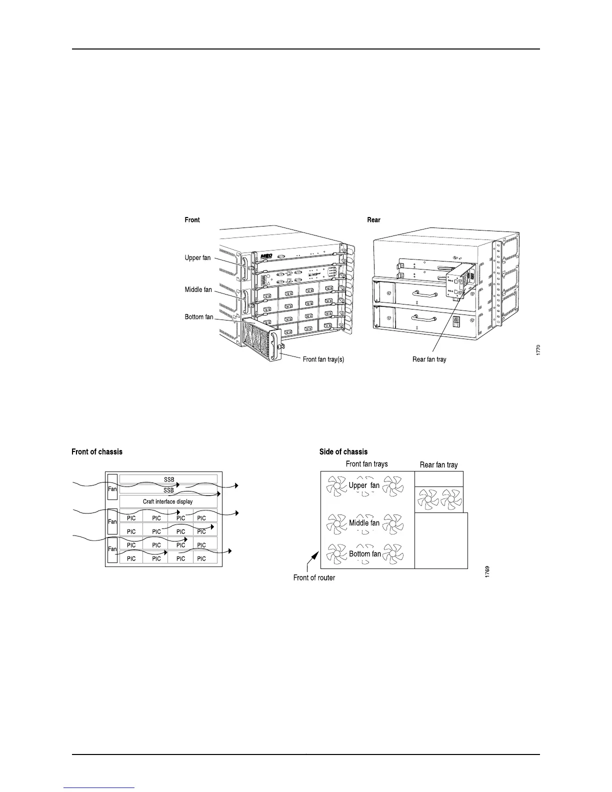
Three front fan trays—Cool the Flexible PIC Concentrators (FPCs) and the System and
Switch Boards (SSBs). The fan trays are located on the left front side of the chassis.
Each tray houses three fans.
•
Routing Engine fan tray—Cools the Routing Engines. The fan tray is located behind the
Routing Engine panel. It houses two fans.
•
Power supply integrated fan—Cools each power supply. It is built into the supply.
Figure 157: M20 Router Cooling System Components
The cooling system includes several fan trays that draw room air into the chassis to keep
its internal temperature below a maximum acceptable level. The cooling subsystems
have redundant components, which are controlled by the SSB. If a fan fails, the remaining
fans provide sufficient cooling for the unit indefinitely (see Figure 158 on page 322).
Figure 158: M20 Router Cooling System and Airflow
Related
Documentation
Checklist for Monitoring the Cooling System on page 317•
M40 Router Cooling System
The M40 router cooling system consists of the following components:
Copyright © 2012, Juniper Networks, Inc.322
M Series and T Series Routers Monitoring and Troubleshooting Guide

 Loading...


