1A-69 Engine General Information and Diagnosis:
P0230-L (Use of SDS)
Specifications
Service Data
B831G21107001
Injector
FI Sensors + Secondary Throttle Valve Actuator
Step Action Yes No
1 1) Turn the ignition switch to OFF.
2) Remove the seat. Refer to “Front Side Exterior Parts
Removal and Installation in Section 9D (Page 9D-6)”.
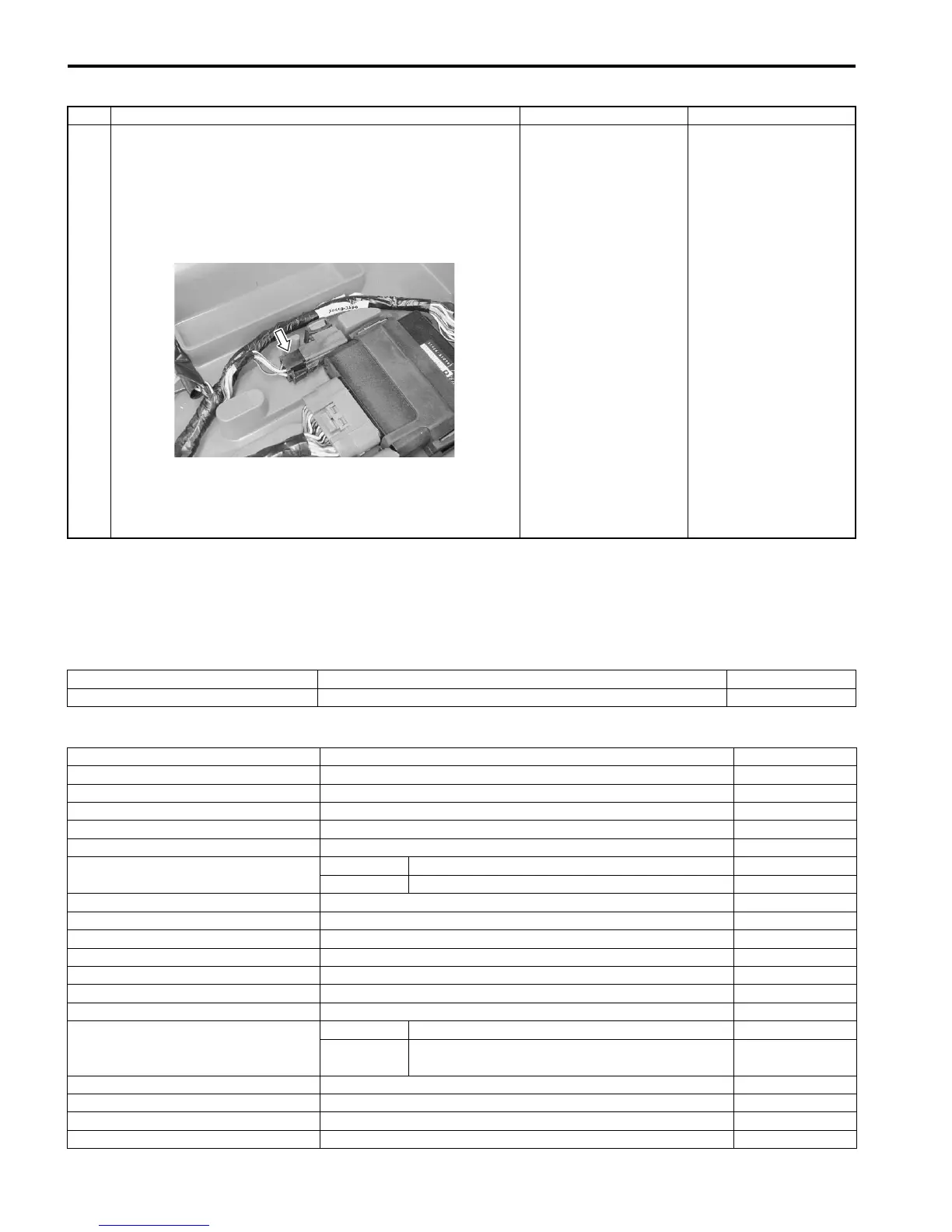
3) Check the FP relay coupler for loose or poor contacts.
If OK, then check the FP relay. Refer to “Fuel Pump
Relay Inspection in Section 1G (Page 1G-7)”.
Is the FP relay OK?
• Y/Bl wire open or
poor “19” connection.
• O/W wire open or
shorted to ground.
• R/B or Y/R wire open
or shorted to ground
or poor “16”
connection.
• If wire and
connection are OK,
intermittent trouble or
faulty ECM.
• Recheck each
terminal and wire
harness for open
circuit and poor
connection.
• Replace the ECM
with a known good
one, and inspect it
again.
Replace the FP relay
with a new one.
I831G1110078-01
Item Specification Note
Injector resistance 11 – 13 Ω at 20 °C (68 °F) —
Item Specification Note
CKP sensor resistance 150 – 250 Ω
CKP sensor peak voltage 5.0 V and more When cranking
IAP sensor input voltage 4.5 – 5.5 V
IAP sensor output voltage Approx. 2.63 V at idle speed
TP sensor input voltage 4.5 – 5.5 V
TP sensor output voltage
Closed Approx. 1.1 V
Opened Approx. 4.3 V
ECT sensor input voltage 4.5 – 5.5 V
ECT sensor output voltage 0.15 – 4.85 V
ECT sensor resistance Approx. 2.45 kΩ at 20 °C (68 °F)
IAT sensor input voltage 4.5 – 5.5 V
IAT sensor output voltage 0.15 – 4.85 V
IAT sensor resistance Approx. 1.60 kΩ at 20 °C (68 °F)
TO sensor resistance 19 – 20 kΩ
TO sensor voltage
Normal 0.4 – 1.4 V
Leaning 3.7 – 4.4 V
When leaning
65°
GP switch voltage 0.6 V and more From 1st to Top
Injector voltage Battery voltage
Ignition coil primary peak voltage 80 V and more When cranking
ISC valve resistance Approx. 31 kΩ at 20 °C (68 °F)

 Loading...


