Automatic Transmission: 5A-11
7) Install the spacer (6).
NOTE
When installing the spacer, press down the
movable drive face plate so as not to cause
the rollers to come out of position.
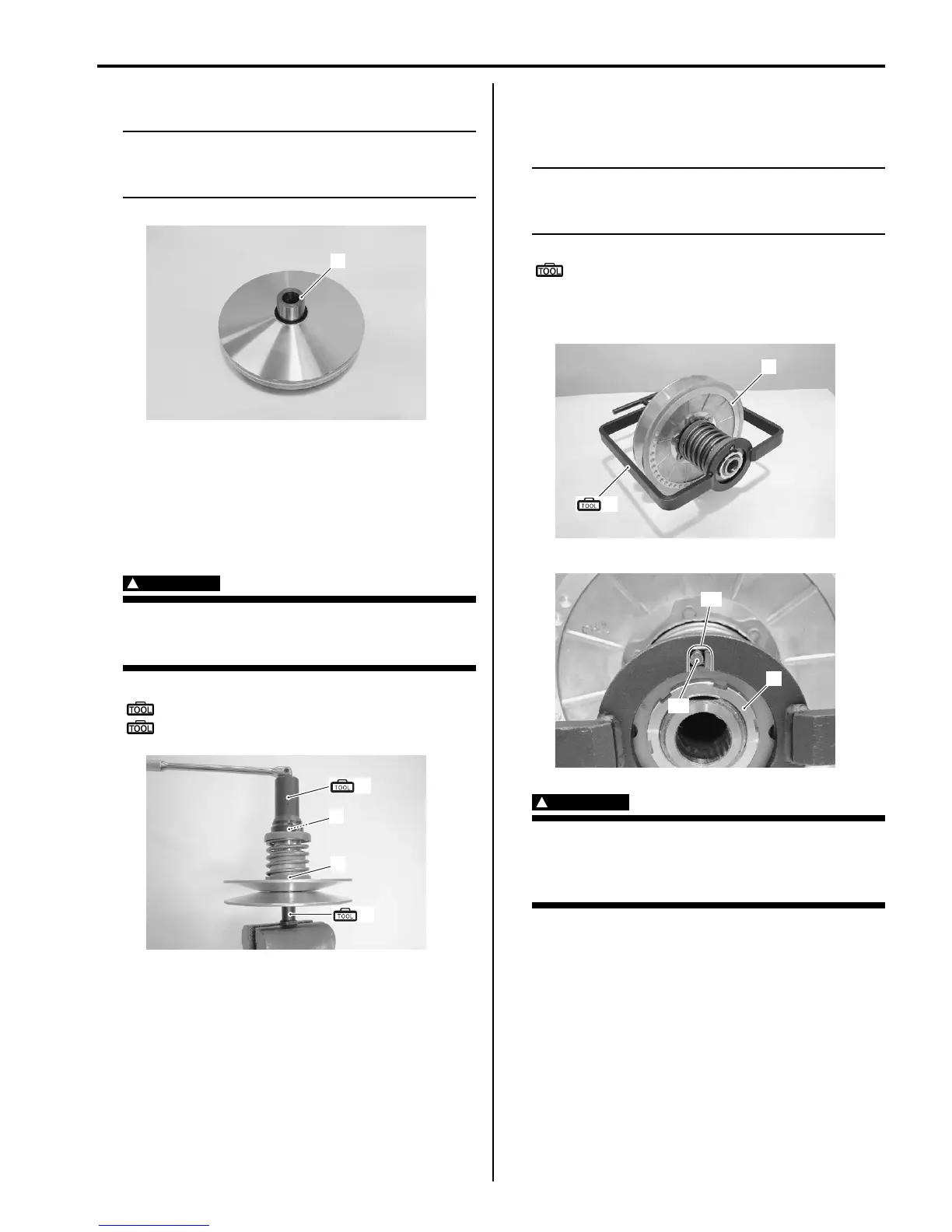
Movable Driven Face Disassembly and
Assembly
B831G25106007
1) Hold the movable driven face assembly (1) with the
special tool and vise, loosen the movable driven face
ring nut (2) with the special tool.
WARNING
!
Do not remove the movable driven face ring
nut before attaching the clutch spring
compressor.
Special tool
(A): 09917–23711 (Ring nut wrench)
(B): 09924–52450 (Fixed driven face holder)
2) Set the special tool to the movable driven face
assembly (1) and compress the movable driven face
assembly by turning in the special tool handle.
NOTE
Make sure to insert the spring end “A” into
the slot “B” of the special tool as shown in
the figure.
Special tool
(c): 09922–31430 (Clutch spring
compressor)
3) Remove the movable driven face ring nut (2).
WARNING
!
Since a high spring force applies to the
movable driven face, care must be used so
as not to cause the movable driven face to
come off abruptly.
6
I831G1510033-01
(A)
(B)
1
2
I831G1510034-01
(C)
1
I831G1510035-01
“A”
“B”
2
I831G1510036-02

 Loading...


