4A-7 Brake Control System and Diagnosis:
7) Loosen the air bleeder valve and pump the brake
lever until the old brake fluid flows out of the brake
system.
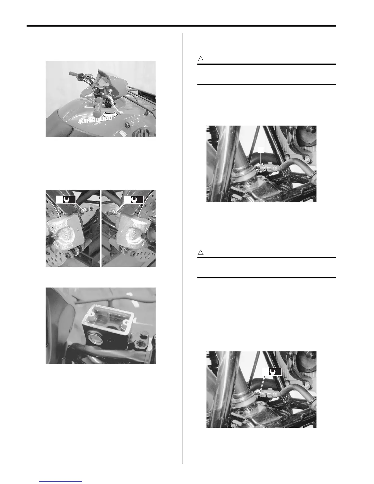
8) Close the air bleeder valve (1) and disconnect the
clear hose.
Tightening torque
Front brake air bleeder valve (a): 6 N·m (0.6 kgf-
m, 4.5 lb-ft)
9) Fill the reservoir with brake fluid.
10) Install the reservoir cap.
11) Install the front wheels. Refer to “Front / Rear Wheel
Removal and Installation in Section 2D (Page 2D-
2)”.
Front Brake Hose Removal and Installation
B831G24106011
Removal
CAUTION
!
Make sure that the vehicle is supported
securely.
1) Drain brake fluid. Refer to “Brake Fluid Replacement
(Page 4A-6)”.
2) Loosen the flare nuts (1) and disconnect the brake
pipe.
3) Remove the front brake hoses as shown in the front
brake hose routing diagram. Refer to “Front Brake
Hose Routing Diagram (Page 4A-1)”.
Installation
CAUTION
!
The seal washers should be replaced with the
new ones to prevent fluid leakage.
1) Install the front brake hose as shown in the front
brake hose routing diagram. Refer to “Front Brake
Hose Routing Diagram (Page 4A-1)”.
2) Tighten the brake flare nut (1) to the specified
torque.
Tightening torque
Brake pipe flare nut (a): 16 N·m (1.6 kgf-m, 11.5
lb-ft)
3) Bleed air from the front brake system. Refer to “Air
Bleeding from Front Brake Fluid Circuit (Page 4A-
5)”.
I831G1410012-01
(a)
1
(a)
1
I831G1410013-01
I831G1410036-01
1
I831G1410014-01
(a)
1
I831G1410015-01

 Loading...


