4A-1 Brake Control System and Diagnosis:
Brake
Brake Control System and Diagnosis
Schematic and Routing Diagram
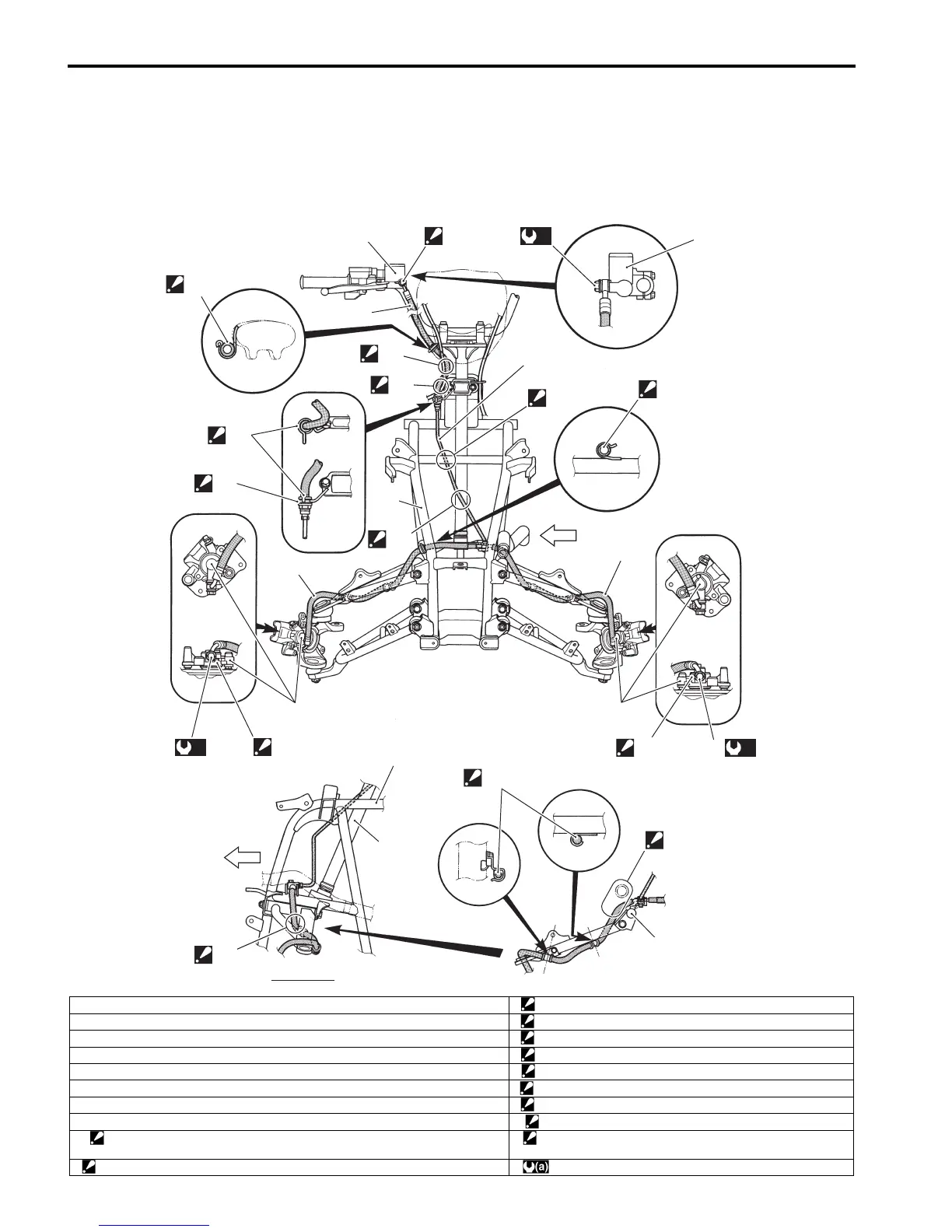
Front Brake Hose Routing Diagram
B831G24102001
1
1
2
3
5
5
4
6
6
“D”
“A”
“D”
“E”
“F”
“C”
“G”
“D”
“J”
“I”
6
FWD
VIEW A
7
9
9
“H”
“B”
4
A
8
(a)
8
(a)
8
(a)
I831G1410001-09
1. Master cylinder reservoir “B”: Pass the brake hose inside the throttle cable.
2. Front brake hose No. 1 “C”: Pass the brake hose outside the throttle cable.
3. Front brake pipe “D”: Fix the brake hose to the it guide firmly.
4. Front brake hose No. 2 “E”: Face the black mark on the brake hose to forward.
5. Front brake caliper “F”: Tighten flare nut firmly.
6. Frame “G”: Pass the brake pipe front of the steering shaft.
7. Steering shaft “H”: Pass the brake pipe behind the frame bridge.
8. Union bolt “I”: Pass the brake hose inside of the suspension arm.
9. Stopper
: After the brake hose union has contacted the stopper, tighten the union bolt.
“J”: Pass the brake hose under the radiator hose.
“A”: After the brake hose union has contacted the reservoir bottom. : 23 N⋅m (2.3 kgf-m, 16.5 lb-ft)

 Loading...


