2D-2 Wheels and Tires:
Front / Rear Wheel Removal and Installation
B831G22406002
NOTE
The front and rear wheels are installed
symmetrically and therefore the removal
procedure for one side is the same as that for
the other side.
Removal
1) Place the vehicle on level ground.
2) Support the vehicle with a jack or wooden block.
3) Remove the wheel nuts (1).
4) Remove the wheel.
Installation
Install the wheel in the reverse order of removal. Pay
attention to the following points:
• Install the wheel and tighten the wheel nuts
temporarily.
WARNING
!
The directional arrow on the tire should point
to the wheel rotation, when remounting the
wheel.
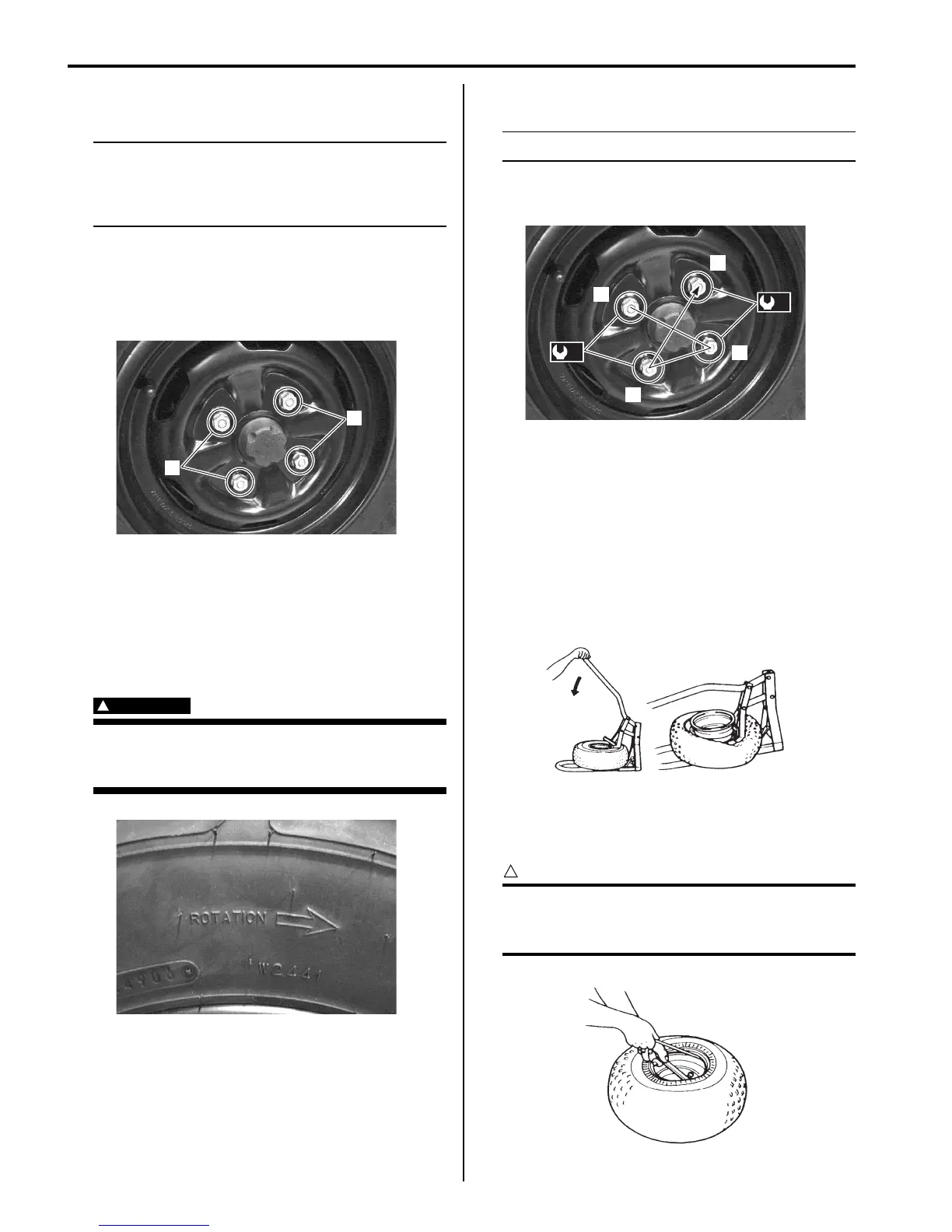
• Tighten the wheel nuts to the specified torque.
NOTE
Tighten the wheel nuts diagonally.
Tightening torque
Wheel nut (a): 60 N·m (6.0 kgf-m, 43.5 lb-ft)
Tire Removal and Installation
B831G22406003
1) Remove the wheel from vehicle. Refer to “Front /
Rear Wheel Removal and Installation (Page 2D-2)”.
2) After removing the air valve caps, release the tire
pressure by depressing the valves.
3) Dismount the bead from the rim completely as
shown in the figure.
4) Separate the tire from the rim using a set of tire
levers and rim protectors.
CAUTION
!
When using the tire levers, do not scratch or
hit the sealing portion (hump) of the wheel or
it may cause air-leakage.
1
1
I831G1240002-01
I831G1240003-01
1
2
3
4
(a)
(a)
I831G1240004-01
I831G1240005-01
I831G1240006-01

 Loading...


