Charging System: 1J-9
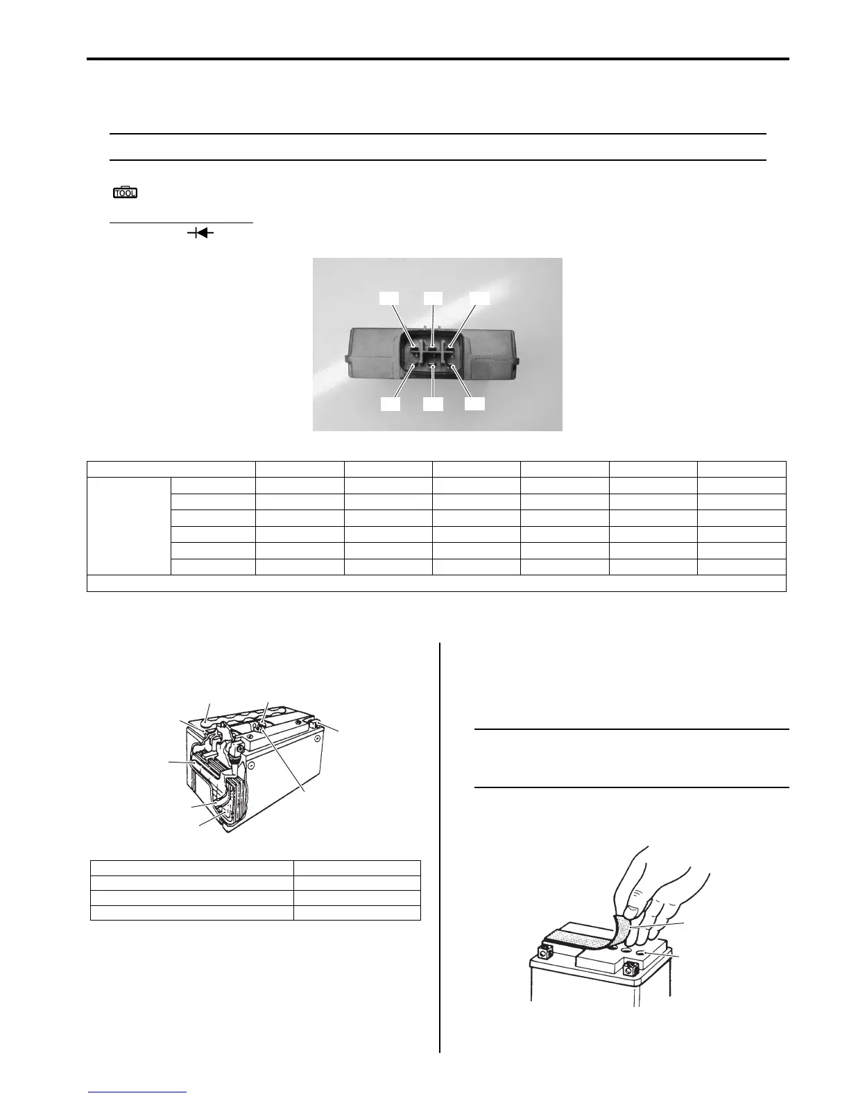
4) Measure the voltage between the terminals using the multi-circuit tester as indicated in the following table. If the
voltage is not within the specified value, replace the regulator/rectifier with a new one.
NOTE
If the tester reads 1.4 V and below when the tester probes are not connected, replace its battery.
Special tool
: 09900–25008 (Multi-circuit tester set)
Tester knob indication
Diode test ( )
Unit: V
5) Connect the regulator/rectifier coupler and reinstall the removed parts.
Battery Components
B831G21A06006
Battery Charging
B831G21A06007
Initial Charging
Filling electrolyte
NOTE
When filling electrolyte, the battery must be
removed from the vehicle and must be put on
the level ground.
1) Remove the aluminum tape (1) which seals the
battery filler holes “A”.
“C”“A” “B”
“D” “E”
“F”
I831G11A0027-01
“A” “B” “C” “D” “E” “F”
(–) probe of
tester to:
“A” — * 0.4 – 1.2 0.3 – 0.7 0.3 – 0.7 0.3 – 0.7
“B”*—****
“C”**—***
“D” * * 0.3 – 0.7 — * *
“E” * * 0.3 – 0.7 * — *
“F” * * 0.3 – 0.7 * * —
*1.4 V and more (tester’s battery voltage)
1. Anode plates 5. Stopper
2. Separator (Fiberglass plate) 6. Filter
3. Cathode plates 7. Terminal
4. Upper cover breather 8. Safety valve
1
3
2
4
5
6
7
8
I649G11A0046-03
1
“A”
I649G11A0039-03

 Loading...


