9C-5 Combination Meter / Fuel Meter / Horn:
Fuel Level Indicator Inspection
B831G29306007
Inspect the fuel level indicator in the following procedures:
1) Move the rear fender upside. Refer to “Fuel Tank Pressure Control (FTPC) Valve Removal and Installation in
Section 1G (Page 1G-12)”.
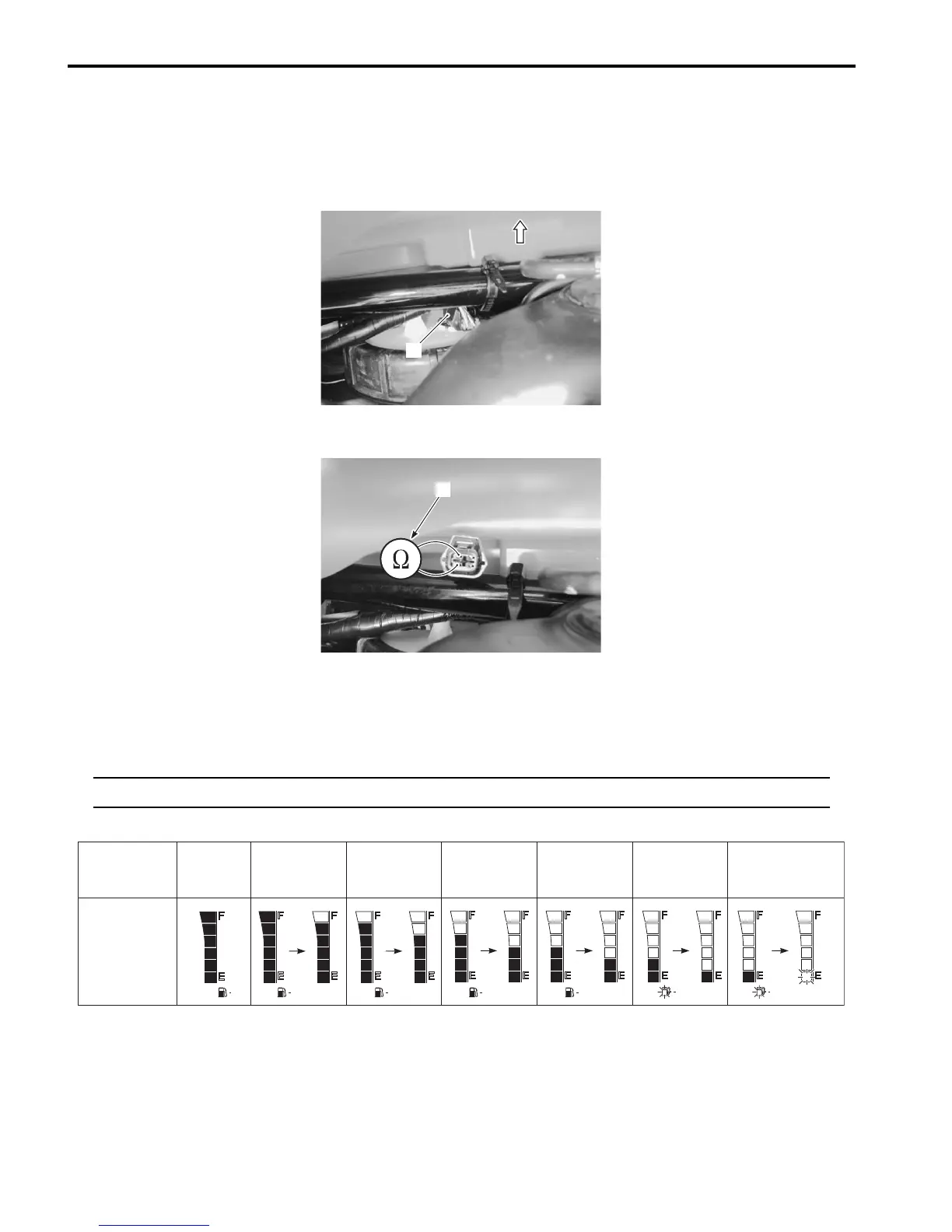
2) Disconnect the fuel level gauge coupler (1).
3) Connect the variable resister (2) between the Y/B and B lead wires from the wire harness.
4) Turn the ignition switch ON.
5) Check the display of fuel level indicator (LCD) as shown in the figure.
If any abnormality is found, replace the combination meter with a new one. Refer to “Combination Meter Removal
and Installation (Page 9C-3)”.
NOTE
It takes approx. 13 seconds that the fuel level indicator indicates the detected fuel level.
6) Connect the fuel level gauge coupler and reinstall the removed parts.
1
I831G1930011-01
2
I831G1930012-02
Resistance
Fuel level
meter
16.5 – 21.5 Ω
23.5 – 30.5 Ω
33 – 41 Ω
53 – 65 Ω 82 – 100 Ω
164 – 208 Ω
Flicker
Flicker Flicker
Less than
16 Ω
ON ON ON ON ON
I831G1930013-04

 Loading...


