3D-6 Propeller Shafts:
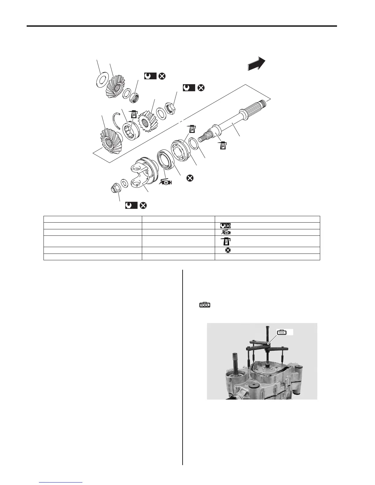
Rear Output Shaft Components
B831G23406005
Rear Output Shaft Removal and Installation
B831G23406006
Removal
1) Remove the engine assembly from the frame. Refer
to “Engine Assembly Removal in Section 1D
(Page 1D-13)”.
2) Disassemble the engine top side. Refer to “Engine
Top Side Disassembly in Section 1D (Page 1D-17)”.
3) Separate the crankcase with the special tool. Refer
to “Engine Bottom Side Disassembly in Section 1D
(Page 1D-45)”.
Special tool
(A): 09920–13120 (Crankcase separating
tool)
1
2
3
4
(a)
11
(a)
10
(a)
12
89
6
FWD
5
7
8
13
I831G1340022-05
1. Rear output shaft drive bevel gear 7. Shim(s) 13. Rear output shaft yoke
2. Shim(s) 8. Bearing : 100 N⋅m (10.0 kgf-m 72.5 lb-ft)
3. Rear output shaft driven bevel gear 9. Oil seal : Apply water resistance grease.
4. Front output shaft drive gear 10. Drive bevel gear nut : Apply engine oil.
5. Bearing 11. Rear output shaft nut : Do not reuse.
6. Rear output shaft 12. Output shaft nut
(A)
I831G1340002-03

 Loading...


