Steering / Handlebar: 6B-9
4) Remove the other tie-rod end in the same manner as
described previously.
5) Separate the tie-rod ends (2), nuts (3), (4) and tie-
rods (5).
CAUTION
!
The lock-nuts (3) have left-hand threads.
Installation
Install the tie-rod in the reverse order of removal. Pay
attention to the following points:
• When installing the tie-rods, make sure the short side
“a” of tie-rod come outside.
• Push the tie-rod to tie-rod lock-nut tightening direction.
• Tighten the lock-nuts to the specification.
CAUTION
!
When tightening the lock-nuts, hold the tie-
rod end with a open end wrench.
NOTE
The lock-nuts (1) have left-hand threads.
Tightening torque
Tie-rod lock-nut (a): 29 N·m (2.9 kgf-m, 21.0 lbf-ft)
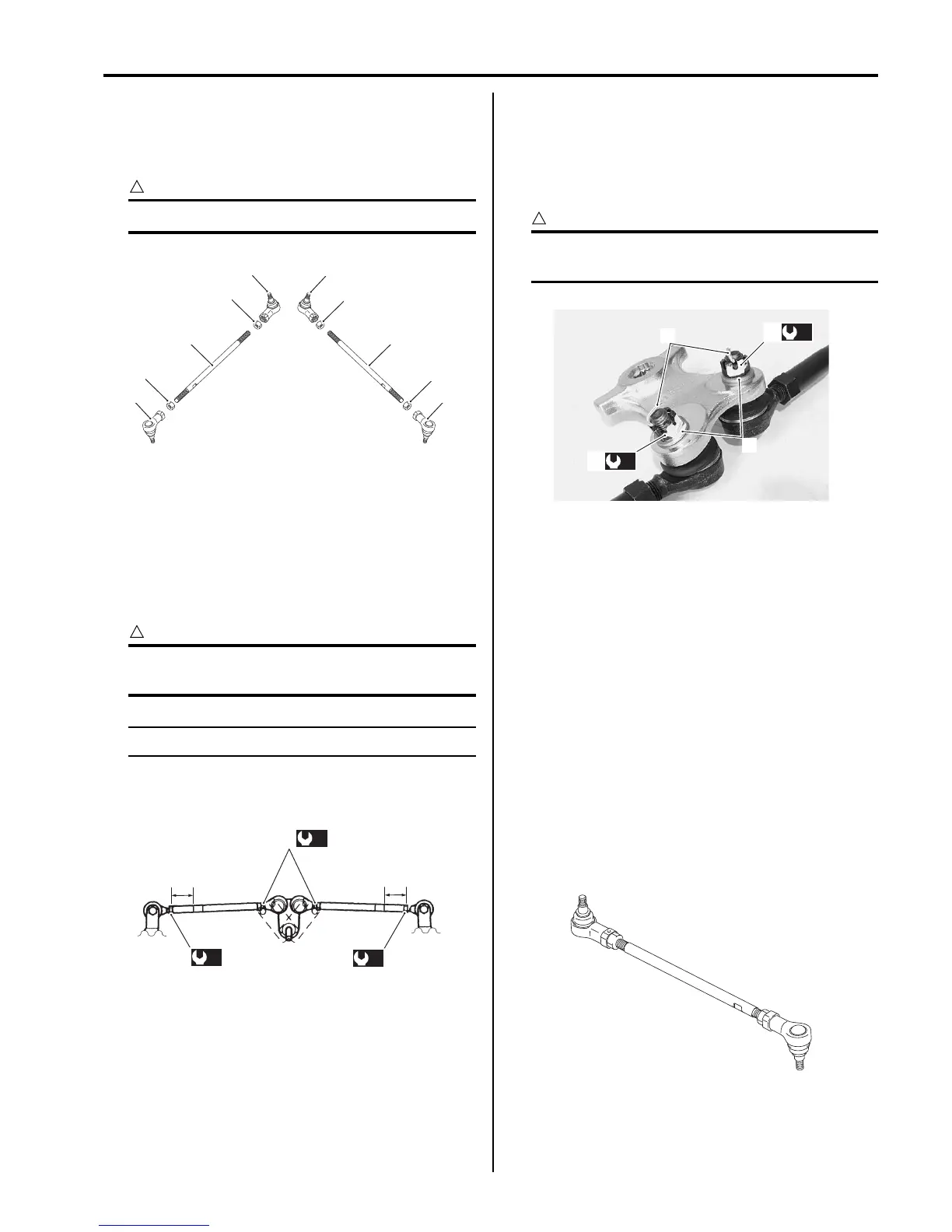
• Install the washers (2) and tighten the rod end nuts (3)
(steering arm plate side) to the specified torque.
Tightening torque
Tie-rod end nut (b): 29 N·m (2.9 kgf-m, 21.0 lbf-ft)
• Install the cotter pins (4).
CAUTION
!
The removed cotter pins (4) must be replaced
with new ones.
• Install the tie-rod ends (steering knuckle side). Refer
to “Front Wheel Hub / Steering Knuckle Removal and
Installation in Section 2B in related manual”.
• After installed wheels, inspect the toe-out. If the toe-
out is out of specification, bring it into the specified
range. Refer to “Steering System Inspection in
Section 0B in related manual” and “Toe Adjustment
(LT-A750XP/ZK9) in Section 0B (Page 0B-2)”.
Steering Related Parts Inspection (LT-A750XP/
ZK9)
B931G46206014
Refer to “Steering Shaft Removal and Installation (LT-
A750XP/ZK9) (Page 6B-6)” and “Tie-rod / Tie-rod End
Removal and Installation (LT-A750XP/ZK9) (Page 6B-
8)”.
Tie-rod
Inspect the tie-rod for distortion or damage. If any
defects are found, replace the tie-rod with a new one.
2
2 2
2
3
4
4
5 5
3
I831G1620039-02
“a”
“a”
(a)
1
(a)
(a)
I831G1620040-03
4
2
(b)
3
(b)
3
I931G3620023-01
I931G3620024-01

 Loading...


