3B-20 Differential:
4) Apply 12 V to the terminal “B” and “E” ((+) to “E” and
(–) to “B”), check the insulation between “A” and “D”.
If any abnormality is found, replace the 4WD/diff-lock
relay with a new one.
Special tool
: 09900–25008 (Multi-circuit tester set)
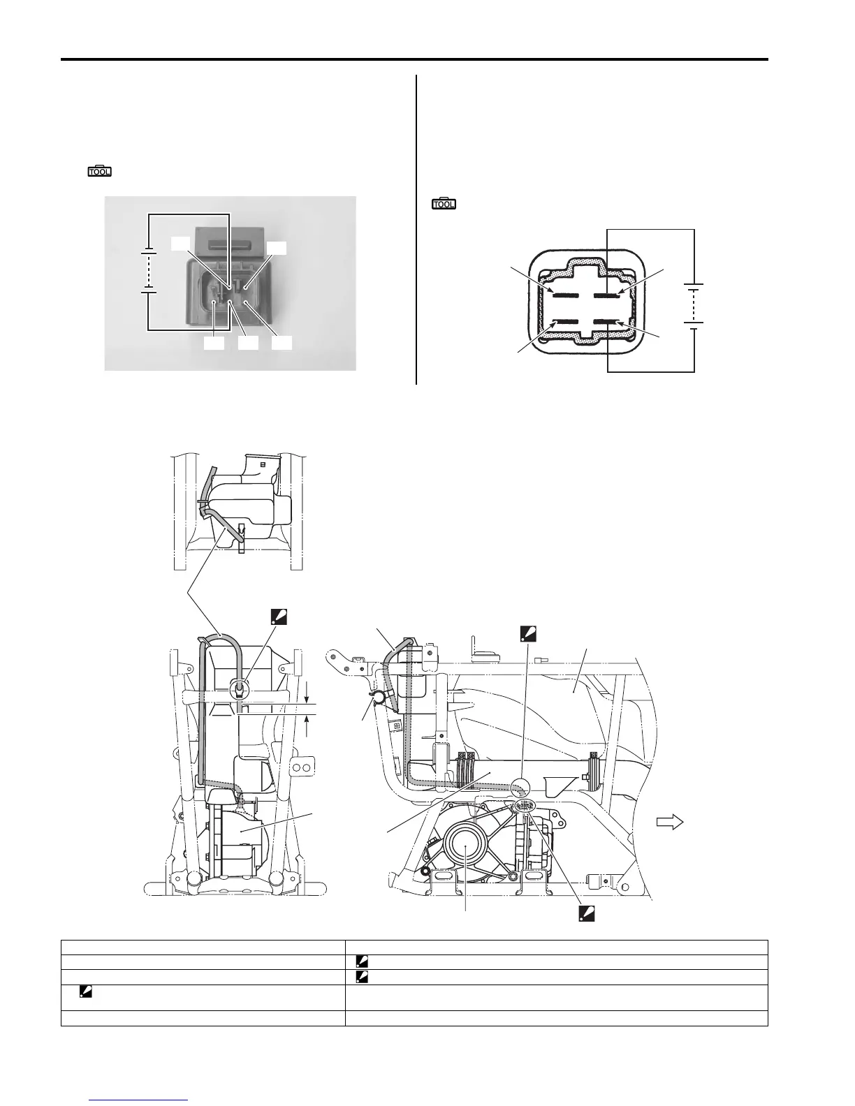
Diff-lock Relay
Check the insulation between “A” and “B” terminals with
the multi-circuit tester. Then Apply 12 V to the terminal
“C” and “D” ((+) to “C” and (–) to “D”), check the
continuity between “A” and “B”. If there is no continuity,
replace the diff-lock relay with a new one.
Special tool
: 09900–25008 (Multi-circuit tester set)
Rear Drive Breather Hose Routing Diagram
B831G23206011
“D”
“E”
“F”
“A”
“B”
I831G1320078-03
“A”
“B”
“C”
“D”
I831G1320079-02
1
2
2
3
1
5
6
“A”
“B”
“a”
FWD
4
I831G1320145-02
1. Breather hose 6. V-belt cooling duct
2. Rear drive assembly “A”: Press the breather hose between the fuel tank lower cover and belt cooling duct.
3. Clamp “B”: Face the tip of clip to forward.
4. Clamp
: Set the clamp to the concave of belt cooling duct.
“a”: 20 – 30 mm (0.79 – 1.18 in)
5. Fuel tank

 Loading...


