Engine General Information and Diagnosis: 1A-4
Schematic and Routing Diagram
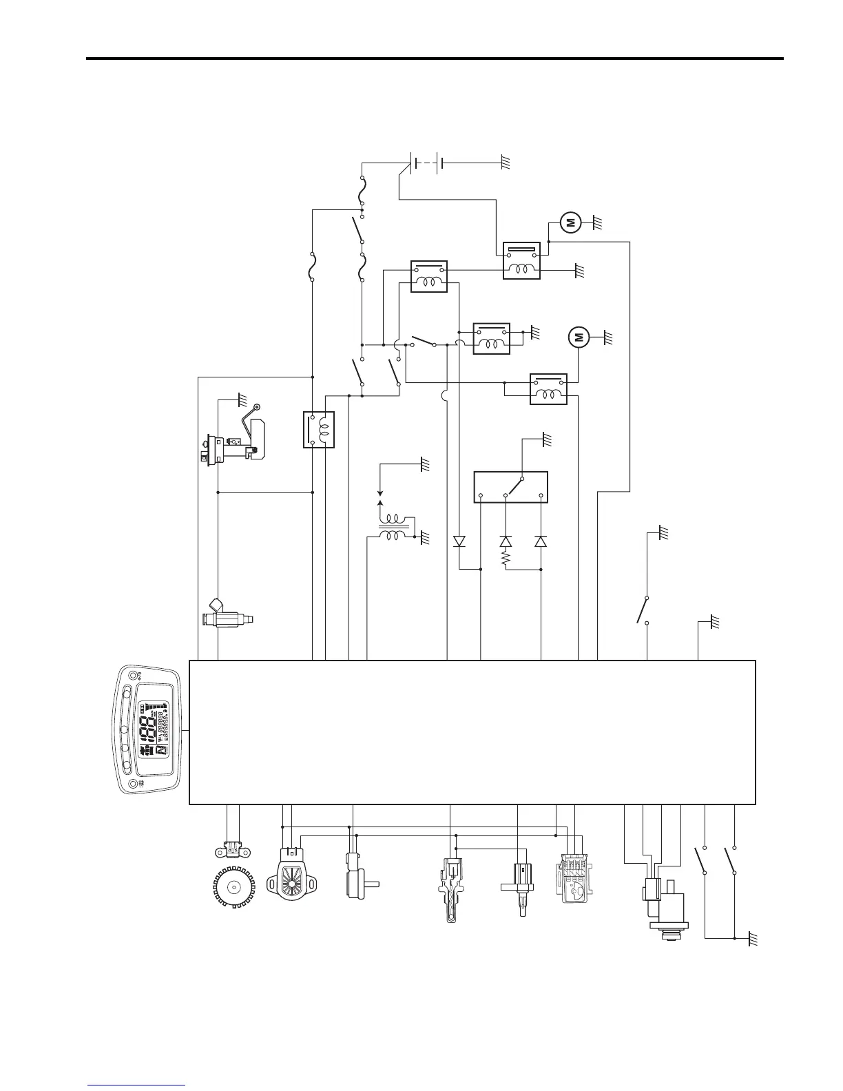
FI System Wiring Diagram
B831G21102001
Crankshaft position sensor
(CKP sensor)
Throttle position sensor
(TP sensor)
Intake air pressure sensor
(IAP sensor)
Engine coolant temperature
sensor
(ECT sensor)
Intake air temperature sensor
(IAT sensor)
Tip-over sensor
(TO sensor)
ISC valve
Diff-lock switch
Diff-lock
relay
Starter
relay
Neutral
relay
Brake
switch (L)
Ignition
switch
Ignition
coil
Fuel injector
Fuel pump relay
Fuel pump
Engine stop
switch
START
button
Starter
motor
Parking
brake
relay
Diff-lock position switch
Override switch
Gear position
switch
N
L
H
30 A15 A
10 A
Speedometer
23
9
18
6
14
13
11
28
24
10
17
34
16
33
29
15
4
2
20
19
3
1
5
26
8
21
12
25
7
1 k
Ω
I831G1110002-04

 Loading...


