1C-6 Engine Electrical Devices:
Installation
NOTE
When replacing the ISC valve, turn the
ignition switch ON and OFF.
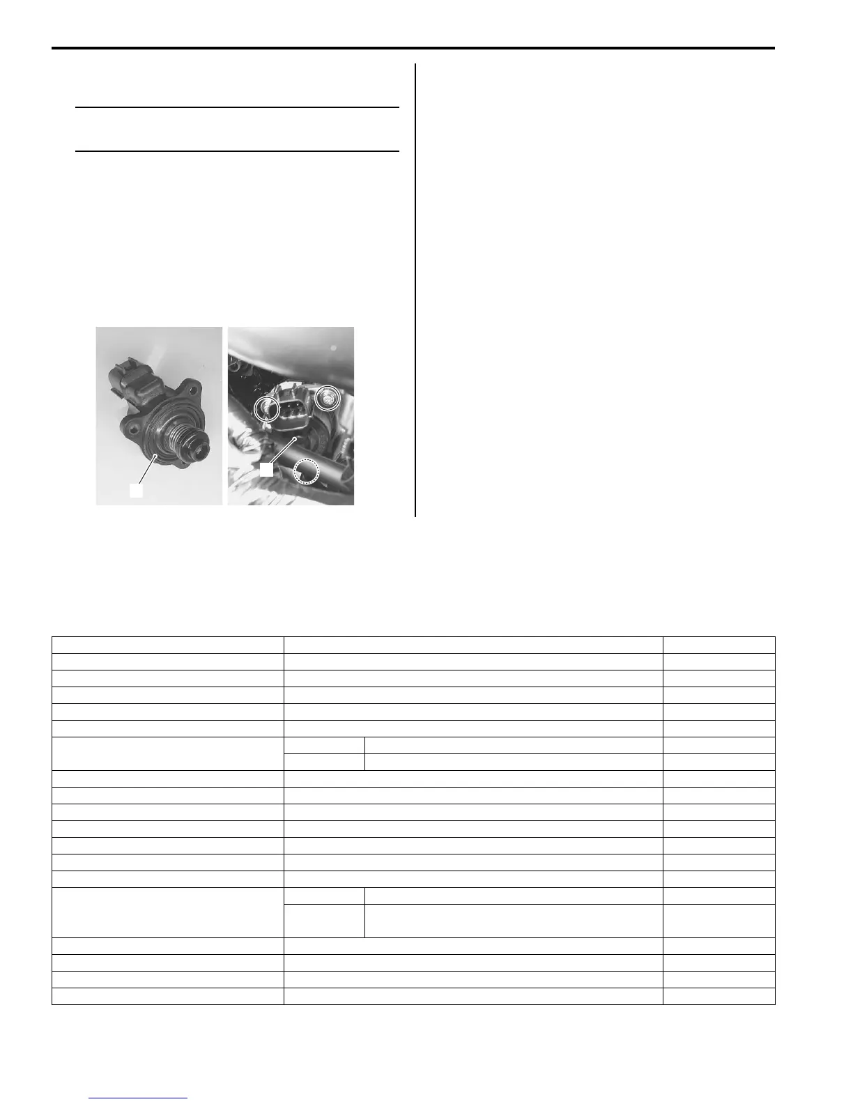
Install the ISC valve in the reverse order of removal.
Pay attention to the following points:
• Install the new O-ring (1).
• Install the ISC valve (2) and tighten the ISC valve
mounting screws to the specified torque.
Tightening torque
ISC valve mounting screw: 2 N·m (0.2 kgf-m, 1.5
lb-ft)
GP Switch Inspection
B831G21306017
Refer to “Gear Position Switch Inspection in Section 1I
(Page 1I-9)”.
GP Switch Removal and Installation
B831G21306018
Refer to “Gear Position (GP) Switch Removal and
Installation in Section 3C (Page 3C-13)”.
Specifications
Service Data
B831G21307001
FI Sensors
2
1
I831G1130015-01
Item Specification Note
CKP sensor resistance 150 – 250 Ω
CKP sensor peak voltage 5.0 V and more When cranking
IAP sensor input voltage 4.5 – 5.5 V
IAP sensor output voltage Approx. 2.63 V at idle speed
TP sensor input voltage 4.5 – 5.5 V
TP sensor output voltage
Closed Approx. 1.1 V
Opened Approx. 4.3 V
ECT sensor input voltage 4.5 – 5.5 V
ECT sensor output voltage 0.15 – 4.85 V
ECT sensor resistance Approx. 2.45 kΩ at 20 °C (68 °F)
IAT sensor input voltage 4.5 – 5.5 V
IAT sensor output voltage 0.15 – 4.85 V
IAT sensor resistance Approx. 1.60 kΩ at 20 °C (68 °F)
TO sensor resistance 19 – 20 kΩ
TO sensor voltage
Normal 0.4 – 1.4 V
Leaning 3.7 – 4.4 V
When leaning
65°
GP switch voltage 0.6 V and more From 1st to Top
Injector voltage Battery voltage
Ignition coil primary peak voltage 80 V and more When cranking
ISC valve resistance Approx. 31 kΩ at 20 °C (68 °F)

 Loading...


