1F-3 Engine Cooling System:
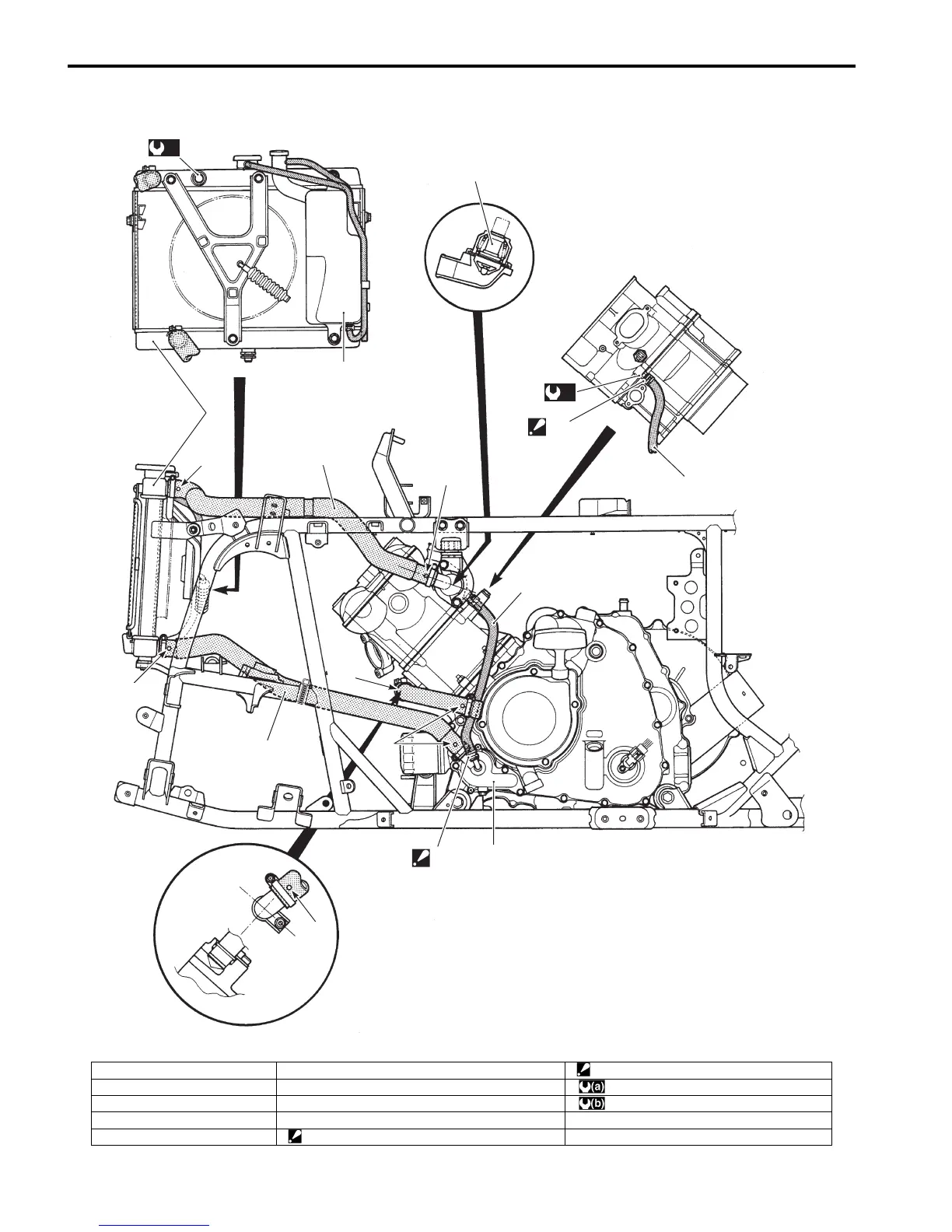
Water Hose Routing Diagram
B831G21602002
1
2
3
4
5
“D”
5
6
7
“C”
“A”
“B”
“B”
“A”
“A”
(a)
(b)
“A”
I831G1160002-05
1. Thermostat 6. Radiator outlet hose “D”: Face the tip of the clip to upper.
2. Radiator 7. Water pump : 17 N⋅m (1.7 kgf-m, 12.5 lb-ft)
3. Reservoir tank “A”: Yellow mark : 12 N⋅m (1.2 kgf-m, 8.5 lb-ft)
4. Radiator inlet hose “B”: White mark
5. Bypass hose “C”: Face the tip of the clip to forward.

 Loading...


