1I-9 Starting System:
Parking Brake Relay Inspection
B831G21906011
Inspect the parking brake relay in the following
procedures:
1) Remove the parking brake relay. Refer to “Parking
Brake Relay Removal and Installation (Page 1I-8)”.
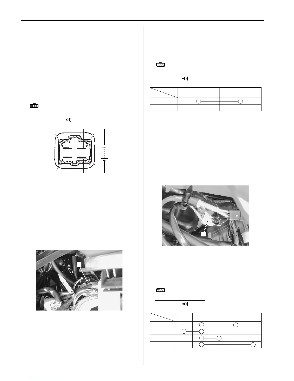
2) Check the insulation between “A” and “B” terminals
using the multi-circuit tester.
3) Apply 12 V to terminals “C” and “D” ((+) to “C” and (–
) to “D”) and check the continuity between “A” and
“B”. If there is no continuity, replace the parking
brake relay with a new one.
Special tool
: 09900–25008 (Multi-circuit tester set)
Tester knob indication
Continuity test ( )
4) Install the parking brake relay in the reverse order of
removal.
Parking Brake Switch Inspection
B831G21906012
Inspect the parking brake switch in the following
procedures:
1) Remove the left inner fender. Refer to “Front Side
Exterior Parts Removal and Installation in Section
9D (Page 9D-6)”.
2) Disconnect the brake switch coupler (1).
3) Inspect the parking brake switch for continuity with a
tester. If any abnormality is found, replace the
parking brake switch with a new one. Refer to
“Handlebars Removal and Installation in Section 6B
(Page 6B-3)”.
Special tool
: 09900–25008 (Multi-circuit tester set)
Tester knob indication
Continuity ( )
4) After finishing the parking brake switch inspection,
reinstall the removed parts.
Gear Position Switch Inspection
B831G21906013
Inspect the gear position switch in the following
procedures:
1) Remove the left side cover and engine side cover.
Refer to “Front Side Exterior Parts Removal and
Installation in Section 9D (Page 9D-6)”.
2) Disconnect the gear position switch coupler (1).
3) Inspect the gear position switch for continuity with a
tester. If any abnormality is found, replace the gear
position switch with a new one. Refer to “Gear
Position (GP) Switch Removal and Installation in
Section 3C (Page 3C-13)”.
Special tool
: 09900–25008 (Multi-circuit tester set)
Tester knob indication
Continuity ( )
“B”
“A”
“C”
“D”
I831G1190020-01
1
I831G1190021-01
WBl
Color
Position
ON
OFF
I831G1190022-01
1
I831G1190023-01
Color
H
L
N
R
Position
W
BlBGR
I831G1190024-02

 Loading...


