Ignition System: 1H-6
CKP Sensor Resistance
1) Remove the left side cover and engine side cover.
Refer to “Front Side Exterior Parts Removal and
Installation in Section 9D (Page 9D-6)”.
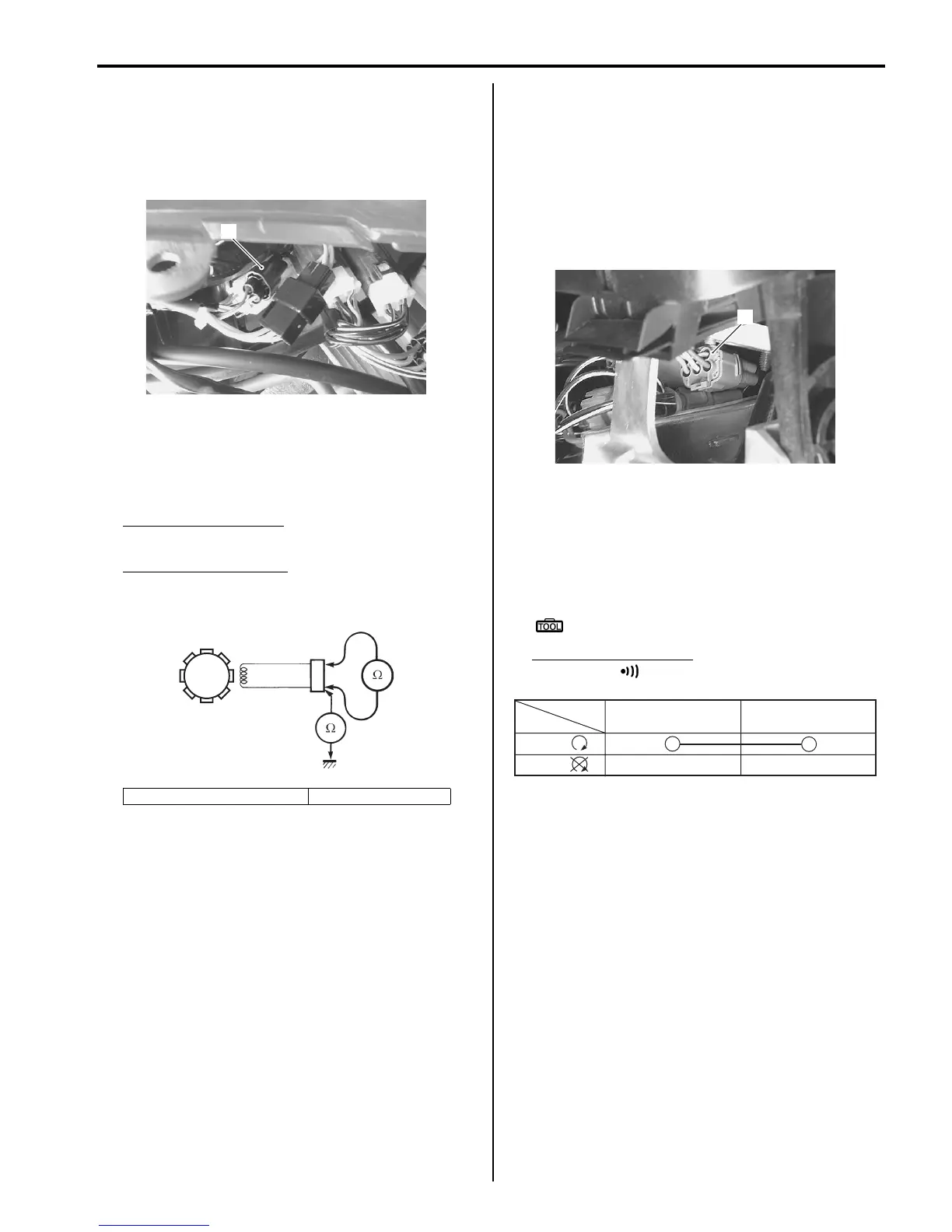
2) Disconnect the CKP sensor coupler (1).
3) Measure the resistance between the lead wires and
ground. If the resistance is not within the standard
range, replace the CKP sensor with a new one.
Refer to “CKP Sensor Removal and Installation
(Page 1H-6)”.
Tester knob indication
Resistance (Ω)
CKP sensor resistance
150 – 250 Ω (Blue – Green)
∞ Ω (Blue – Ground)
4) After measuring the CKP sensor resistance, reinstall
the removed parts.
CKP Sensor Removal and Installation
B831G21806005
Refer to “Generator Removal and Installation in Section
1J (Page 1J-4)”.
Engine Stop Switch Inspection
B831G21806006
Inspect the engine stop switch in the following
procedures:
1) Turn the ignition switch OFF.
2) Remove the left inner fender. Refer to “Front Side
Exterior Parts Removal and Installation in Section
9D (Page 9D-6)”.
3) Disconnect the handlebar switch coupler (1).
4) Inspect the engine stop switch for continuity with a
tester.
If any abnormality is found, replace the handlebar
switch assembly with a new one. Refer to
“Handlebars Removal and Installation in Section 6B
(Page 6B-3)”.
Special tool
: 09900–25008 (Multi-circuit tester set)
Tester knob indication
Continuity ( )
5) After finishing the engine stop switch inspection,
reinstall the removed parts.
Ignition Switch Inspection
B831G21806007
Refer to “Ignition Switch Inspection in Section 9C
(Page 9C-7)”.
2. CKP sensor coupler 3. CKP sensor
1
I831G1180008-01
3
2
I718H1180008-02
1
I831G1180010-01
O O/W
Color
Position
OFF
RUN
()
()
I831G1180009-01

 Loading...


