1C-2 Engine Electrical Devices:
IAP Sensor Removal and Installation
B831G21306005
Removal
1) Remove the left inner fender. Refer to “Front Side
Exterior Parts Removal and Installation in Section
9D (Page 9D-6)”.
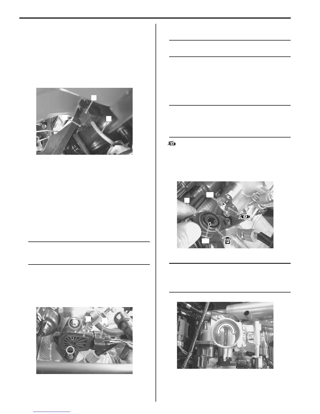
2) Disconnect the IAP sensor coupler (1) and vacuum
hose (2).
3) Remove the IAP sensor (3).
Installation
Install the IAP sensor in the reverse order of removal.
TP Sensor Inspection
B831G21306006
Refer to “DTC “C14” (P0120-H/L): TP Sensor Circuit
Malfunction in Section 1A (Page 1A-34)”.
TP Sensor Removal and Installation
B831G21306007
Removal
NOTE
Prior to disassembly, mark sensor original
position with a paint or scribe for accurate
reinstallation.
1) Remove the air cleaner box. Refer to “Air Cleaner
Box Removal and Installation in Section 1D
(Page 1D-5)”.
2) Disconnect the TP sensor coupler (1) and remove
the TP sensor (2).
Installation
NOTE
When replacing the TP sensor, turn the
ignition switch ON and OFF.
Install the TP sensor in the reverse order of removal.
Pay attention to the following points:
• Apply a thin coat of engine oil to the O-ring.
• Install the TP sensor (1) and tighten the TP sensor
mounting screw to the specified torque.
NOTE
• Align the throttle shaft end “A” with the
groove “B” of TP sensor.
• Apply grease to the throttle shaft end “A” if
necessary.
: Grease 99000–25010 (SUZUKI SUPER
GREASE A or equivalent)
Tightening torque
TP sensor mounting screw: 2 N·m (0.2 kgf-m, 1.5
lb-ft)
NOTE
Make sure the TP valve open or close
smoothly. If the TP sensor adjustment is
necessary, refer to “TP Sensor Adjustment
(Page 1C-3)”.
1
2
3
I831G1130003-01
1
2
I831G1130004-01
1
“B”
“A”
I831G1130005-01
I831G1130006-01

 Loading...


