e-STUDIO556/656/756/856(Ver03) © 2012 TOSHIBA TEC CORPORATION All rights reserved
DISASSEMBLY AND REPLACEMENT
4 - 30
[ 2 ] e-STUDIO556/656
4.4.3 Laser control PC board (PLG board)
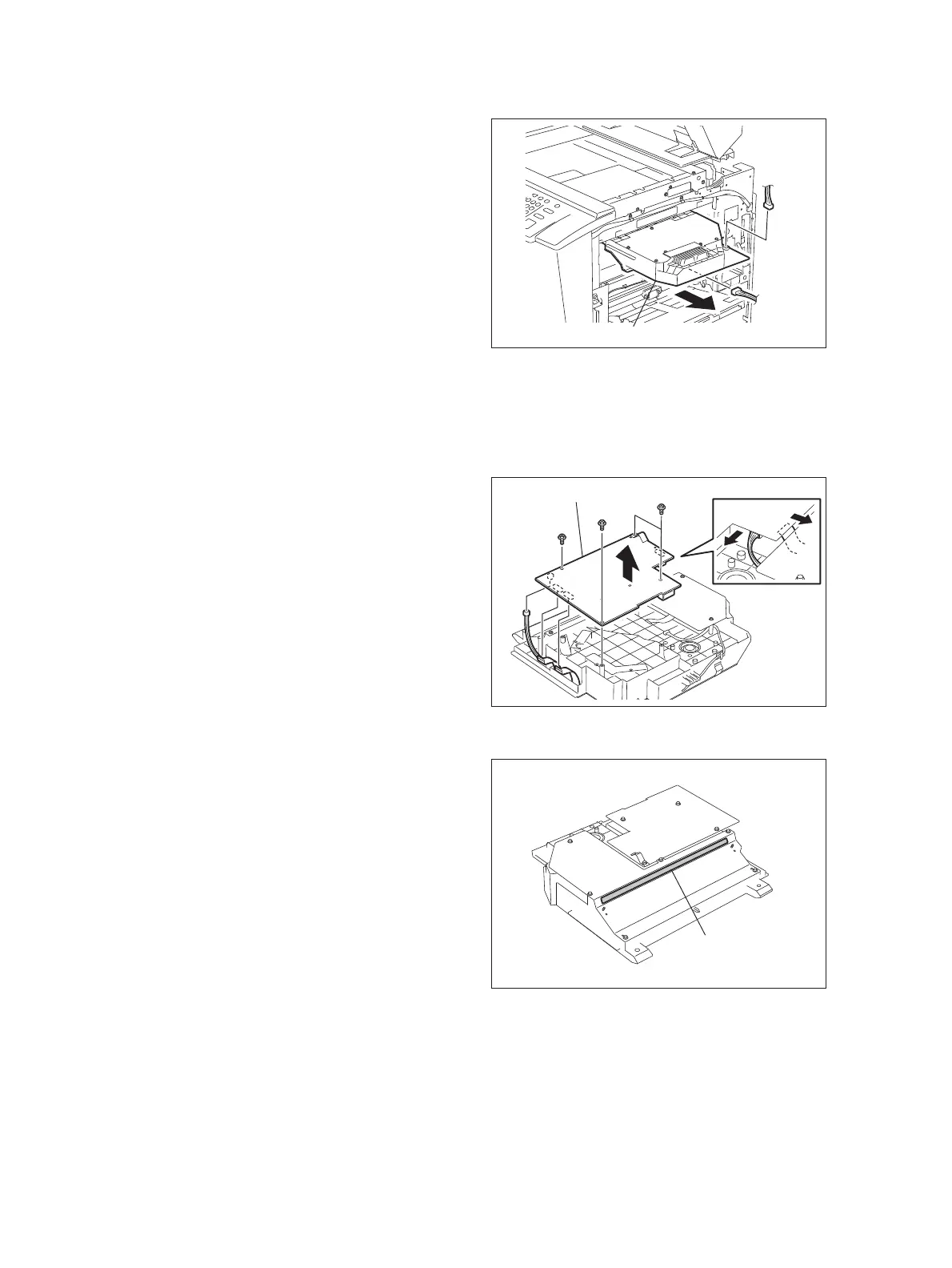
(1) Disconnect 2 connectors and pull out the
laser unit.
Fig. 4-83
(1) Remove the laser optical unit.
( P.4-29 "4.4.2 Laser optical unit")
(2) Disconnect 3 connectors.
(e-STUDIO756/856: 5 connectors)
(3) Remove 4 screws and take off the Laser
control PC board (PLG board).
Fig. 4-84
1. Do not leave fingerprints or stain on the
slit glass.
2. Pay close attention not to make an impact
or vibration on the laser optical unit
because it is a precise apparatus.
3. Place the removed laser optical unit so as
not to load on the polygonal motor.
4. Do not disassemble the laser optical unit
in the field because it is precisely
adjusted and very sensitive to dust and
stain.
Fig. 4-85
Laser optical unit
Laser control PC board
Slit glass
 Loading...