e-STUDIO556/656/756/856(Ver03) © 2012 TOSHIBA TEC CORPORATION All rights reserved
ADJUSTMENT
6 - 46
6.9 Adjustment of the Scanner Section
6.9.1 Adjustment carriages-1 and -2 positions
<Procedure>
(1) Take off the RADF.
(2) Take off the original glass.
(3) Take off the top right cover.
(4) Take off the top rear cover.
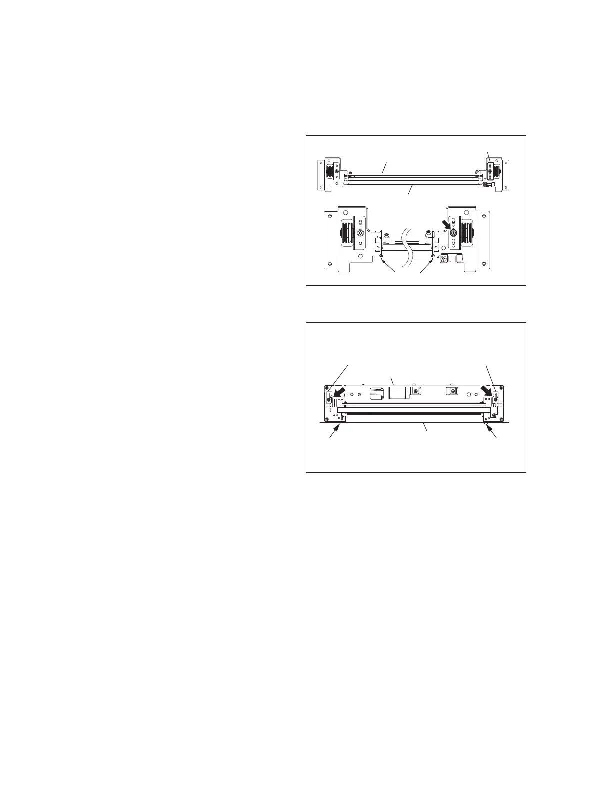
(5) Move the carriage-2 toward the exit side.
Rotate the drive pulley to move the carriage.
(6) Loosen the screws fixing the front side pulley
bracket, make the sections A and B of the
carriage-2 touch with the inside of the exit
side frame and screw them up.
Make sure that the sections A and B of the
carriage-2 touch with the exit side frame.
Fig. 6-28
(7) Put carriage-1 on the rail. Then make
sections C and D of carriage-1 touch the
inside of the exit side frame and tighten the
front and rear sides of the bracket with the
screws.
Fig. 6-29
B
A
Carriage-2
Pulley bracket
Exit side frame
Enlarged view of carriage
[
Rear
] [Front]
Carriage-1
[
Rear
]
[
Front
]
D
C
Bracket
Bracket
Exit frame
Enlarged view of carriage
 Loading...