4
© 2012 TOSHIBA TEC CORPORATION All rights reserved e-STUDIO556/656/756/856(Ver03)
DISASSEMBLY AND REPLACEMENT
4 - 101
4.10.5 Upper separation finger unit / Upper separation finger
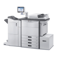
(4) Open 2 clamps and remove 2 connectors.
(5) Remove 2 screws and take off the bracket.
Fig. 4-281
When installing the bracket, be sure that the
harnesses are not caught.
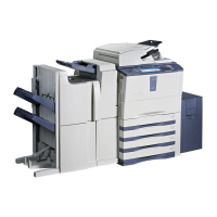
(6) Pull out the IH coil.
When installing the IH coil, be sure that the
marks "C" and "S" of the power supply
harnesses come at the left side.
Fig. 4-282
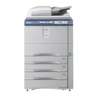
(1) Take off the fuser unit.
( P.4-96 "4.10.2 Fuser unit")
(2) Take off the cleaning web unit.
( P.4-97 "4.10.3 Cleaning web unit /
Cleaning web")
(3) Remove 2 screws to take off the fuser unit
cover (front).
(4) Remove 2 stepped screws. Then take off the
upper separation finger unit and a crank
bracket by sliding them to the rear side.
Fig. 4-283
Bracket
Clamp
Connector
Screw
IH coil
C
(
Blue
)
S
(
Red
)
Black
Crank plate
Upper separation finger unit
Screw Screw
 Loading...