4
© 2012 TOSHIBA TEC CORPORATION All rights reserved e-STUDIO556/656/756/856(Ver03)
DISASSEMBLY AND REPLACEMENT
4 - 111
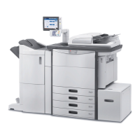
4.11.5 Exit cover switch [SW5]
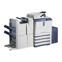
4.11.6 Gate solenoid [SOL2]
(1) Take off the left lower cover (= exit cover).
( P.4-4 "4.1.11 Left lower cover (Exit
cover)")
(2) Open the exit/reverse unit. Then disconnect
the connector and release the latch to take
off the exit cover switch.
Fig. 4-310
(1) Take off the left lower cover (= exit cover).
( P.4-4 "4.1.11 Left lower cover (Exit
cover)")
(2) Open the exit/reverse unit. Then disconnect
1 connector, release the clamp and remove 3
screws to take off the gate solenoid.
Fig. 4-311
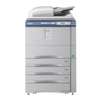
The solenoid is normally screwed at the
position A shown in the figure at right.
However, the position of the solenoid can be
adjusted by moving this screw to the position
B when the flap valve of the solenoid is not
pulled enough.
Fig. 4-312
Exit cover switch
Gate solenoid
 Loading...