9
© 2012 TOSHIBA TEC CORPORATION All rights reserved e-STUDIO556/656/756/856(Ver03)
REPLACEMENT OF PC BOARDS / HDD
9 - 3
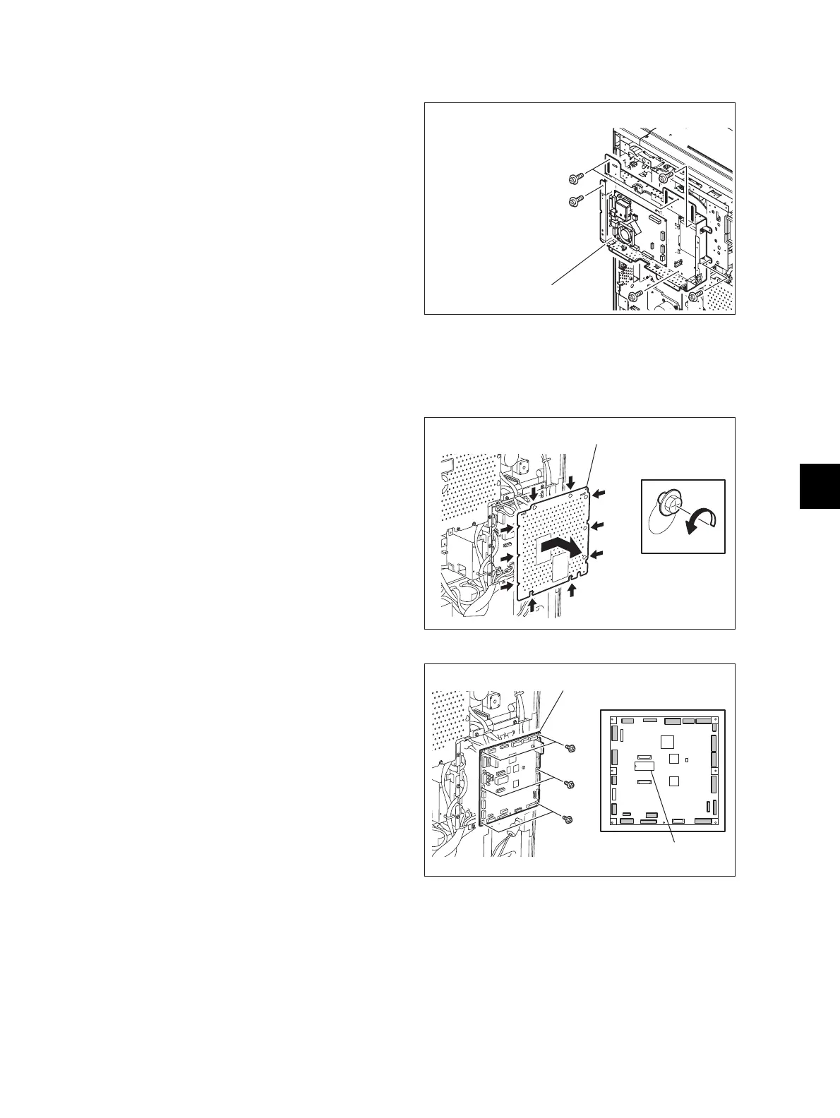
9.1.3 SYS board case
9.1.4 Logic PC board (LGC board)
(1) Take off the SYS board cover.
P.9-1 "9.1.1 SYS board cover"
(2) Remove 8 screws to take off the SYS board
case [9.1.3].
When any option is installed, take off the
option first and then take off the SYS board.
Fig. 9-6
(1) Take off the rear cover.
( P.4-5 "4.1.13 Rear cover")
(2) Loosen 8 screws and take off the LGC board
cover by sliding it to the right side.
Fig. 9-7
(3) Disconnect 20 connectors of the LGC board.
(4) Remove 6 screws to take off the LGC board.
When replacing the LGC board, remove
IC27 from the old board and then install it on
the new one.
• When installing NVRAM(IC27), be sure
that its pins are attached in the correct
direction and not misaligned.
• Do not touch the pins of NVRAM(IC27)
with your bare hands. (Be careful of static
electricity.)
• Replace the LGC board following "9.2.5
Procedures and settings when replacing
the SLG board".
Fig. 9-8
 Loading...