e-STUDIO556/656/756/856(Ver03) © 2012 TOSHIBA TEC CORPORATION All rights reserved
DISASSEMBLY AND REPLACEMENT
4 - 96
4.10.2 Fuser unit
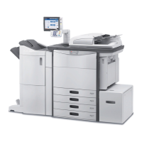
(4) Disconnect 3 connectors and remove 6
screws to take off the IH board.
Fig. 4-270
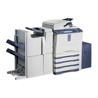
(1) Remove 2 screws and open the IH cover-1
carefully to the front side.
(2) Remove 2 screws to take off a knob cover.
Fig. 4-271
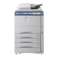
(3) Remove 4 screws and then release 4 power
supply harnesses of the IH coil.
(4) Disconnect 4 connectors.
(5) Remove 2 screws and open the IH cover-2 to
the front side.
Fig. 4-272
Connector
(
Yellow
)
Connector
(
White
)
Connector
Heater control PC board Screw
Screw
Screw
Screw
Connector
Connector
Screw
Screw
Screw
IH cover-2
 Loading...