e-STUDIO556/656/756/856(Ver03) © 2012 TOSHIBA TEC CORPORATION All rights reserved
ADJUSTMENT
6 - 98
(7) The mode LED1~4 light OFF and the writing operation of the tray width adjustment data into the
EEPROM is finished.
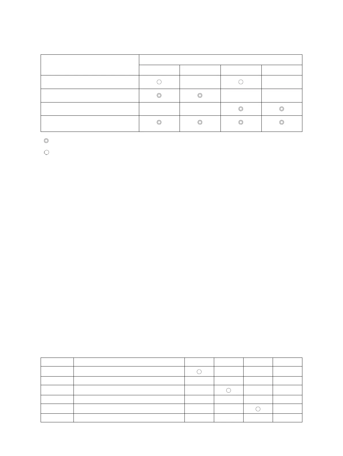
* When the writing into the EEPROM has been finished, make sure to check the result with the
following table.
6.18.2 Input check 1
This is a mode at which the checking of each motor, solenoid and clutch operation is carried out.
(1) Turn ON the power with pressing the control panel mode key and start key. (The start LED blinks
in green.)
(2) Press the mode key and set up the LED1 to blink and LED2~4 to light OFF, and press the start
key. (The start LED lights ON in green.)
* With pressing the mode key for more than 1 sec., all the mode LEDs light OFF and become
able to be reset.
(3) Press the mode key and check the operations referring to the following table. The operational
mode is switched at every time the mode key is pressed.
* Num (at the right table): the number of times which the key is pressed
* At the operational mode 7~36, the motor rotation speed is switched whenever the start key is
pressed. The motor rotation speed can be checked by referring to the mode LED blinking
speed.
Mode LED blinking at 1000msec. cycle: Low speed
Mode LED blinking at 700msec. cycle: Medium speed
Mode LED blinking at 500msec. cycle: High speed 1
Mode LED blinking at 250msec. cycle: High speed 2
Mode LED blinking at 100msec. cycle: High speed 3
Writing result
Mode LED display
LED1 LED2 LED3 LED4
Success - -
Failure (minimum position) - -
Failure (maximum position) - -
Failure (both maximum ) and minimum
positions)
: Blinking
:Light ON
- : Light OFF
*Num. Operation LED1 LED2 LED3 LED4
1 Pickup trigger solenoid ON - - -
2 Pickup trigger solenoid OFF - - - -
3 Pickup clutch ON - - -
4 Pickup clutch OFF - - - -
5 Reverse solenoid ON - - -
6 Reverse solenoid OFF - - - -
 Loading...