e-STUDIO556/656/756/856(Ver03) © 2012 TOSHIBA TEC CORPORATION All rights reserved
REPLACEMENT OF PC BOARDS / HDD
9 - 6
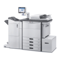
9.1.7 High-voltage transformer (HVT) / LGC board case
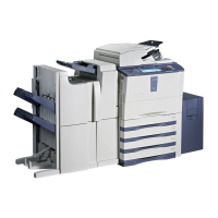
9.1.8 Switching regulator (PS)
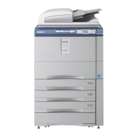
9.1.9 SRAM board (RAM-S)
(1) Take off the LGC board cover.
P.9-3 "9.1.4 Logic PC board (LGC board)"
(2) Disconnect 6 connectors of the high-voltage
transformer.
(3) Remove 1 screw and release 3 locking
supports to take off the high-voltage
transformer.
Fig. 9-15
(1) Take off the rear cover.
( P.4-5 "4.1.13 Rear cover")
(2) Disconnect 12 connectors.
(3) Remove 4 screws and release the hook to
take off the switching regulator.
When installing or taking off the switching
regulator, be sure that their harnesses are
not caught.
Fig. 9-16
(1) Take off the SYS board cover.
( P.9-1 "9.1.1 SYS board cover")
(2) Release 2 latches and take off the SRAM
board for the SYS board with the case.
Fig. 9-17
Locking support
High-voltage transformer
Latch
Latch
Case
 Loading...