6
© 2012 TOSHIBA TEC CORPORATION All rights reserved e-STUDIO556/656/756/856(Ver03)
ADJUSTMENT
6 - 1
6. ADJUSTMENT
6.1 Adjustment Order
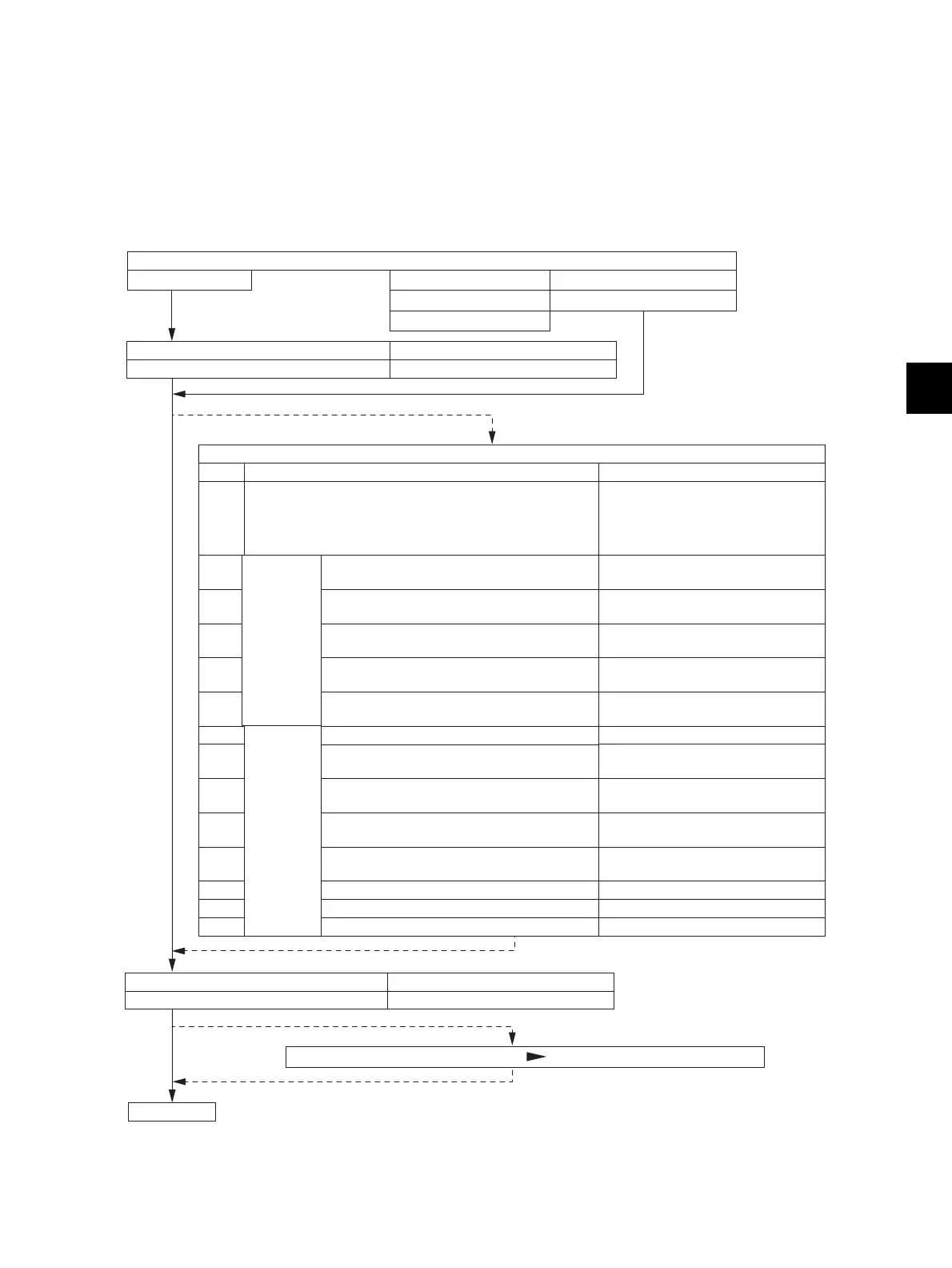
This chapter mainly explains the procedures for image related adjustment. When replacing
components which have other specified instructions for adjustment, those specified instructions are to
be obeyed in priority. In the following diagram, the solid lines with arrow lead to essential adjustments,
while the dotted lines lead to adjustments to be performed if necessary.
Fig. 6-1
Developer material
Parts to be replaced
Photoconductive drum
Main charger grid
Laser optical unit
Drum cleaning blade
Transfer roller
Item to be adjusted Code in mode 05
6.2 Adjustment of the auto-toner sensor 2000
6.3 Image dimensional adjustment
Items
Code in mode 05
6.3.2 Paper alignment at the registration roller
Order
1
2
3
4
5
6
9
8
10
11
12
6.3.4
Scanner
related
adjustment
13
14
7
6.3.3
Printer
related
adjustment
[A] Image distortion
[B] Reproduction ratio adjustment of the
primary scanning direction
[C] Image position adjustment of the
primary scanning direction
[D] Reproduction ratio adjustment of the
secondary scanning direction
[E] Image position adjustment of the
secondary scanning direction
[F] Top margin
[G] Right margin
[H] Bottom margin
[B] Primary scanning data laser writing
start position
[C]Reproduction ratio of secondary
scanning direction
[D] Secondary scanning data laser writing
start position
[E] Primary scanning data laser writing
start position at duplexing
[A] Reproduction ratio of primary
scanning direction
4108, 4109, 4100, 4101, 4110,
4111, 4103, 4104, 4105, 4106,
4107, 4115, 4116, 4117, 4118,
4119, 4120, 4579
4527
-
4402, 4560, 4561, 4058, 4059,
4061, 4063, 4060, 4062
4001
4006
4009
4000
3030
3032
3031
4050
4052
4053
Adjust the image quality if necessary.
END
Code in mode 05
7165
Item to be adjusted
6.4.1 Automatic gamma adjustment
(Chapter 6.3, 6.4, 6.5, 6.6, 6.7)
 Loading...