e-STUDIO556/656/756/856(Ver03) © 2012 TOSHIBA TEC CORPORATION All rights reserved
DISASSEMBLY AND REPLACEMENT
4 - 114
4.11.11 Exit motor [M18]
4.11.12 O-ring
When installing the receiving tray, add the O-rings (service parts) to the exit roller in order to improve
the paper stacking condition.
(1) Take off the reverse section driving unit.
( P.4-112 "4.11.8 Reverse section driving
unit / Reverse motor driving PC board
(MOT2-RV board)")
(2) Take off the rear cover.
( P.4-5 "4.1.13 Rear cover")
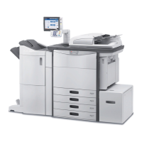
(3) Take off the LGC board cover and disconnect
1 connector.
(4) Remove 2 screws and take off the exit motor.
Fig. 4-319
(1) Remove 6 screws and take off the left lower
cover (exit cover).
( P.4-4 "4.1.11 Left lower cover (Exit
cover)")
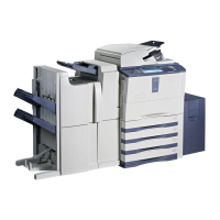
(2) Remove 2 E-rings and move the 2 bearings
toward the inside.
Fig. 4-320
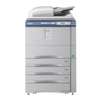
(3) Move the exit roller to the near side and
install 2 O-rings to the grooves of the exit
roller.
O-ring: Refer to the parts list for the parts
number and so on.
Fig. 4-321
Exit motor
E-ring Bearing
O-ring
 Loading...